Axial Flux vs Radial Flux Frameless Motors: The Robotics Sizing and Sourcing Guide
Compare axial vs radial flux frameless torque motors: bearing loads, air gaps, inertia, cooling and total cost. Use the RFQ checklist to size a robot joint kit.
For robotics teams comparing axial flux vs radial flux frameless torque motors, the first decision is packaging: axial flux can fit a wide, shallow joint; radial flux often suits a cylindrical sleeve with a direct stator-to-housing heat path. Neither topology guarantees higher installed torque density, faster acceleration, or lower cost.
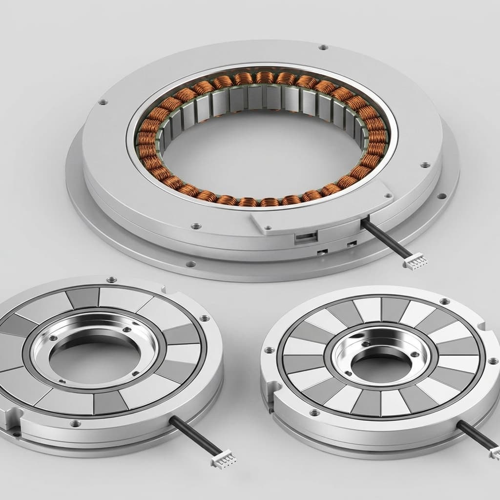
A frameless motor is delivered as an unhoused stator and rotor kit. The OEM supplies the bearings, rotor support, housing, cooling path, and position feedback. Compare the complete actuator at the same duty cycle and temperature limits, rather than comparing a peak motor-kit rating with an installed continuous rating.
Published and reviewed: October 26, 2026. Scope: global OEM robotics, gimbals, and rotary stages using permanent-magnet frameless kits. This is a design-screening guide based on geometric reasoning and the references below, not a measured comparison of supplier samples. Numerical examples use stated assumptions; they are not product ratings, quotations, or bearing approval.
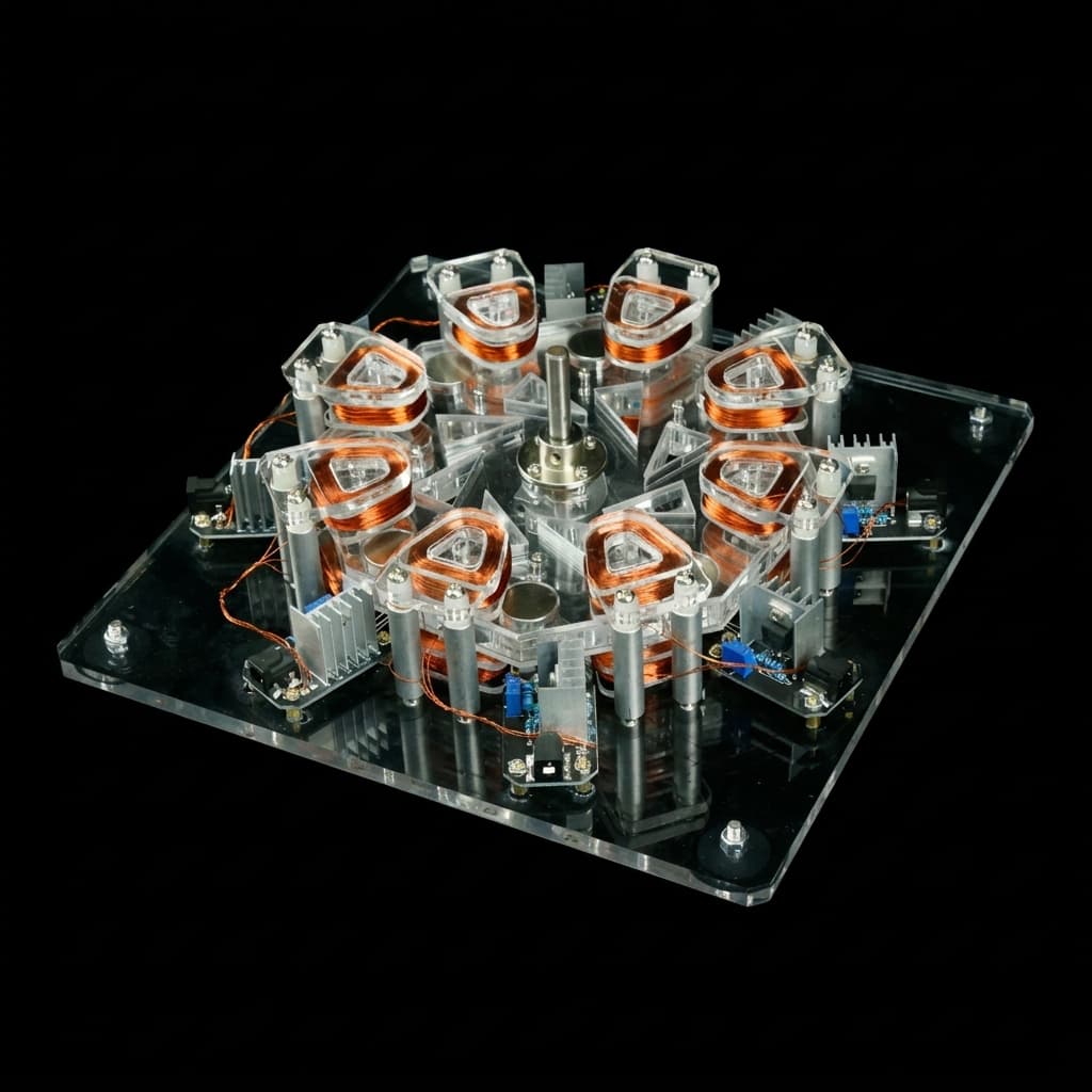
If you already have a joint envelope, compare the integration requirements in our Frameless Torque Motors catalog alongside the checklist below. The cover is a pancake-motor illustration, not evidence of tested performance.
To make an informed selection, engineers and buyers must understand how the magnetic circuit differs geometrically between radial flux and axial flux machines.
Figure 1. Idealized motor sections. A symmetric dual-rotor axial design has a different force balance; the sketch does not predict a bearing load or thermal rating.
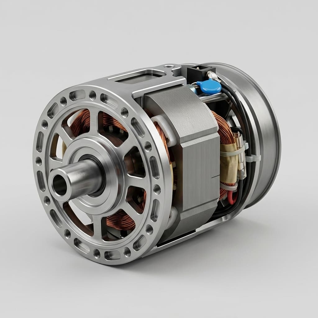
Magnetic flux crosses the cylindrical air gap perpendicular to the shaft. The rotor may sit inside or outside the stator. At approximately constant tangential air gap shear stress, torque scales as T_radial ∝ D² × L_stack, where D is the active gap diameter and L_stack is the active stack length.
In an ideal centered, symmetric machine, radial magnetic forces balance. Eccentricity, housing distortion, and external joint loads can still generate bearing loads; zero net magnetic pull is an idealization, not a bearing specification.
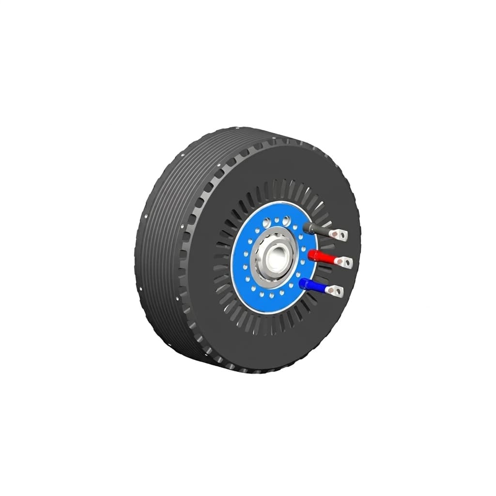
Magnetic flux crosses a planar air gap parallel to the shaft. For one active annular face at uniform tangential shear stress τ, integrating dT = τ × 2πr² dr gives T_axial = (2πτ/3) × (R_o³ − R_i³). Multiple active faces add torque according to their actual loading.
These scaling relations hold shear stress and geometry assumptions fixed. They do not establish a universal torque-density advantage because cooling, electrical loading, inner bore, end windings, and rotor structure differ. Axial windings can shorten end connections, but not all axial topologies eliminate end turns. YASA's technology overview describes a specific automotive axial design; its performance claims are not robot-joint kit ratings.
In a single-sided iron-cored axial flux design, permanent magnets can attract the stator while unpowered. The bearing load depends on which members support the rotor and stator, and where the magnetic force closes through the structure.
For a simplified gap with mainly normal flux, Maxwell pressure gives F_axial ≈ B_g² × A_gap / (2μ₀), where μ₀ = 4π × 10⁻⁷ H/m. This approximation neglects leakage, fringing, slotting, and spatial variation. More generally, integrate the local magnetic stress over the active face rather than squaring a single average field.
Assume an active annulus with outer diameter D_o = 115 mm, inner diameter D_i = 75 mm, and uniform normal gap flux density B_g = 0.82 T across the full annulus:
The result is about 1.6 kN for these assumed inputs, not a measured force or a typical specification for all axial motors. Magnet grade alone does not determine gap flux. Use the supplier's force-versus-gap curve or validated electromagnetic analysis for the real pole coverage and topology.
Bearing capacity and life: Combine magnetic attraction with payload, radial load, overturning moment, speed, and the required life. Deep-groove, angular-contact, and crossed-roller options must be assessed from their actual ratings. THK's cross-roller overview confirms that this bearing arrangement can accept radial, axial, and moment loads; it does not size a bearing for this example.
Drag and efficiency: Include bearing preload, seals, lubrication, and speed in the drag budget. Magnetic attraction is a structural load; it is not automatically equivalent to the bearing's specified preload.
Assembly fixtures: Ask for a controlled rotor installation and removal procedure, guides, and force-rated tooling appropriate to the kit's documented attraction force.
Dual-rotor boundary: A symmetric two-rotor arrangement can balance opposing axial forces on the stator in the ideal centered case. Individual discs and supports remain loaded, and unequal gaps can create residual forces. Confirm the shaft, support, and bearing force paths rather than assuming zero bearing load.
For an axial disc, small relative tilt consumes edge clearance approximately as Δg = R_outer × tan(θ). An illustrative 120 mm outer diameter gives R_outer = 60 mm. At θ = 0.15°, Δg ≈ 0.157 mm. Against an assumed nominal gap of 0.65 mm, tilt alone uses about 24% of the gap.
For a radial machine, tilt can also close the gap. If the tilt pivot is at the middle of an active stack of length L, the end offset is approximately (L/2) × tan(θ). A different pivot location changes the lever arm. Neither topology is immune to misalignment.
Compare the worst-case remaining gap with the motor supplier's required minimum running clearance, including the relevant shock condition. Avoid counting the same tolerance twice. Rotor contact can damage magnets, windings, or the support structure; there is no universal speed threshold for damage.
Procurement rule: Request the allowable runout and displacement limits on a controlled drawing. Material grade or machining tolerance alone cannot approve a housing: verify assembled stiffness, bearing-seat geometry, rotor support, and thermal growth under the specified load cases.
The annular-disc formula assumes uniform mass distribution. At fixed thickness, density, and inner-to-outer radius ratio, mass grows with radius squared and inertia with radius to the fourth power. At fixed mass, the radius dependence differs. A real rotor needs a CAD mass model or a suitable inertia measurement including magnets, adhesive, hubs, and retention parts.
An axial rotor may have a large effective radius, but a radial outer rotor can also carry mass far from the axis. Compare actual candidate inertias at the required hot torque and current limit. For a reducer with ratio n = motor speed / output speed, motor inertia referred to the output is n² × J_rotor; keep all torque and inertia values on the same side of the reducer.
Engineering decision: Request hot torque-speed curves, current definitions, rotor inertia, and the full load motion profile. Acceleration arithmetic is a screening step; servo bandwidth also depends on drive response, feedback, structural resonances, and control tuning.
Continuous torque depends on copper and iron losses, winding and magnet temperature limits, ambient conditions, speed, and the installed cooling path. Insulation class alone is not an allowable operating temperature for every component.
An outer stator can conduct heat through its core and mounting interface into a cylindrical housing. Contact pressure, bond-line thickness, insulation, and jacket conditions determine the thermal resistance; a press fit does not guarantee a particular continuous rating.
A disc stator may reject heat through its rim, hub, conductive support, or direct winding cooling. A coreless layout has a different path from an iron-cored layout. Air gaps impede conduction, but convection and radiation still transfer some heat. YASA's referenced automotive design uses direct oil cooling, illustrating why axial flux is not inherently limited to intermittent service.
For an initial constant-torque-constant copper-loss screen, calculate T_RMS = sqrt(Σ(T_i² × Δt_i) / ΣΔt_i) across the full repeating cycle, including energized holding periods. Compare it with continuous torque under matching mounting and temperature conditions, then check peak torque duration, speed-dependent losses, current, and transient thermal limits separately. Long load periods may exceed thermal time constants even when a cycle average looks acceptable.
The IEC 60034-29:2008 catalog record describes indirect temperature-rise tests for rotating machines where loading to a specified condition is impractical. It is not IEC 60034-1, and the catalog summary does not establish a universal derating factor or certify a frameless kit.
Axial depth constrains the joint: A shallow disc may fit the available diameter while leaving room for bearings, feedback, and mounting hardware.
The force path and gap budget are manageable: Supplier force data and structural analysis support the proposed rotor/stator arrangement.
The installed cooling path meets the duty: Assess continuous running, energized holding, and intermittent motion separately. High holding torque can generate substantial heat at zero speed.
A cylindrical sleeve suits the housing: An outer stator interface can simplify the intended cooling arrangement.
A candidate meets the dynamic target: Its measured or modeled inertia, hot torque, and drive compatibility fit the motion profile.
Available kits reduce integration work: Compare actual drawings, supplier qualifications, sample availability, and dated quotes rather than assuming a universal price or lead-time advantage.
If neither candidate meets the clearance or thermal budget, revise the actuator architecture before selecting a topology. This guide does not replace application-specific mechanical, electromagnetic, or thermal validation.
Use the same requirement set for both topologies so engineering and purchasing can compare usable quotes:
Envelope and tolerancing: Supply OD, through-bore, total axial allowance, mounting method, minimum running gap, allowable runout, and worst-case load displacement.
Magnetic force data: Request force versus gap and displacement, the rotor/stator arrangement, and the proposed load path for assembly and operation.
Motion and inertia: Provide load torque, speed, acceleration, external moments, rotor/load inertia, and reducer ratio if applicable.
Hot performance and drive match: Request torque-speed curves, peak duration, bus voltage, phase-current convention, torque constant convention, winding temperature, and ambient conditions.
Duty and cooling: Include energized holding time, load/unload intervals, housing material and interface, coolant conditions if used, thermal sensor location, and the acceptance temperature-rise test.
Bearing and drag budget: Check combined loads, required life, stiffness, preload, sealing, lubrication, and allowable drag with the bearing supplier.
Insulation and retention: Agree the applicable dielectric test method and voltage for the intended bus and environment, potting specification, magnet temperature limits, rotor retention, and overspeed requirements. No single hipot threshold applies to every kit.
Commercial and acceptance terms: State prototype quantity, annual forecast, delivery country, target date, currency, delivery terms, tooling ownership, sample inspection records, and change-control requirements. Ask for a dated quotation and confirmed lead time.
Possibly, but compare complete joints at the same continuous torque, speed, cooling condition, and duty cycle. Include motor kit, bearings, housing, cooling hardware, and assembly fixtures. A lighter motor kit does not establish a lighter installed actuator.
PCB stators use etched copper conductors instead of wound wire. An ironless implementation can reduce cogging, but copper thickness, current density, heat extraction, voltage insulation, and allowable temperature determine its usable torque. Axial flux alone does not imply a PCB stator or a universal duty limit.
Radial eccentricity can create unbalanced magnetic pull; axial runout can vary the planar gap and magnetic force. Both can affect torque ripple and vibration. Specify allowable runout, mounted torque ripple, and balancing requirements for the actual rotor speed and bearing arrangement; no single balance grade guarantees air gap clearance.
Either can work. Compare hot torque-speed curves, rotor inertia reflected through the reducer, gear efficiency, backlash, backdrivability, and total joint mass. A thin axial motor can help packaging; a radial kit can simplify a cylindrical cooling sleeve. Neither topology determines force-control bandwidth by itself.
Send your envelope drawing, torque-speed cycle, bus/current limits, cooling conditions, quantity, and delivery country to [email protected]. Ask the team to confirm a feasible topology, the evidence needed for acceptance, sample availability, and a project-specific quotation.
Reviewed October 26, 2026. These primary sources support the specific points identified below; none supplies a controlled comparison of robotics frameless kits, a universal price premium, or a promised sample lead time.
YASA — Axial Flux Technology. Manufacturer description of a specific axial topology, shortened windings, and direct oil cooling in automotive motors. Use it as an example of architecture and cooling choices, not independent verification of robot-joint performance. YASA technology overview.
IEC 60034-29:2008 — Rotating electrical machines: Equivalent loading and superposition techniques; indirect testing to determine temperature rise. Official catalog summary of the test-method scope. The full standard and the kit's applicable acceptance requirements must be reviewed separately. IEC publication 134.
THK — Cross-Roller Ring / Double Row Ring. Official description of bearing arrangements supporting radial, axial, and moment loads. Select a model using its detailed ratings and application conditions. THK cross-roller overview.
Can I replace a radial flux motor with an axial flux motor to reduce robot arm weight?
Possibly, but compare complete joints at the same continuous torque, speed, cooling condition, and duty cycle. Include motor kit, bearings, housing, cooling hardware, and assembly fixtures. A lighter motor kit does not establish a lighter installed actuator.
Why do some axial flux motors use PCB stators, and what are their trade-offs?
PCB stators use etched copper conductors instead of wound wire. An ironless implementation can reduce cogging, but copper thickness, current density, heat extraction, voltage insulation, and allowable temperature determine its usable torque. Axial flux alone does not imply a PCB stator or a universal duty limit.
How does rotor eccentricity affect cogging torque in both topologies?
Radial eccentricity can create unbalanced magnetic pull; axial runout can vary the planar gap and magnetic force. Both can affect torque ripple and vibration. Specify allowable runout, mounted torque ripple, and balancing requirements for the actual rotor speed and bearing arrangement; no single balance grade guarantees air gap clearance.
Which topology is better suited for quasi-direct-drive actuators?
Either can work. Compare hot torque-speed curves, rotor inertia reflected through the reducer, gear efficiency, backlash, backdrivability, and total joint mass. A thin axial motor can help packaging; a radial kit can simplify a cylindrical cooling sleeve. Neither topology determines force-control bandwidth by itself.
Author
Matthew Lindholm - Principal Electromagnetic Drive Specialist
Principal Electromagnetic Drive Specialist specializing in high-torque-density motor topologies, slotless/frameless stator-rotor thermal management, and industrial motion control.