Frameless Motor Air Gap Eccentricity and UMP: Bearing Loads, Tolerances, and Assembly Guide
Frameless torque motor air gap eccentricity and UMP: compare bearing loads, tolerance budgets, assembly methods, and inspection limits. Prepare your OEM RFQ.
When engineering teams transition from traditional geared servo drives to direct-drive frameless torque motors, they gain zero backlash, extreme torsional stiffness, and compact packaging. However, they also inherit a critical mechanical responsibility: establishing, tolerancing, and preserving the motor air gap.
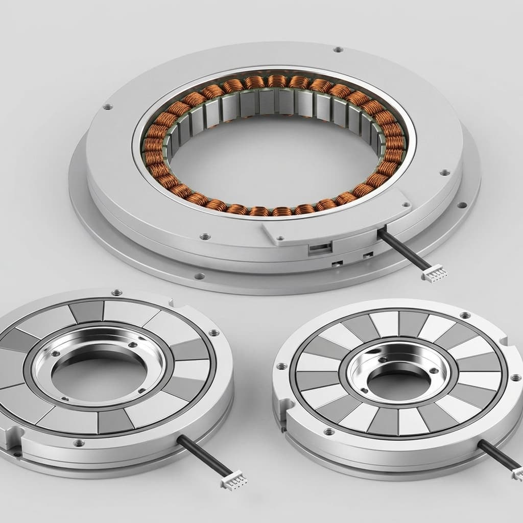
In a standard housed servo motor, the motor manufacturer grinds the shaft, seats the internal bearings, line-bores the end bells, and verifies the air gap before shipment. In contrast, a frameless motor is delivered as an unhoused stator lamination stack and a bare permanent-magnet rotor ring. The customer's housing structure, shaft machining, bearing selection, and assembly tooling dictate whether the rotor spins on a perfect magnetic center or deflects into destructive mechanical failure.
The frameless torque motor air gap must come from the selected motor drawing; there is no universal clearance for every frame. This guide uses a 0.50 mm nominal radial gap as an illustrative design case. Mechanical runout, housing deflection, or thermal growth can shift the rotor off-center and generate Unbalanced Magnetic Pull (UMP), a radial force that reduces the assembly's effective restoring stiffness.
This guide provides mechanical joint architects, robotics engineers, and procurement specialists with a comprehensive engineering framework for air gap tolerancing, UMP quantification, bearing fatigue life calculations, assembly fixture design, and RFQ specifications.
Published and technically reviewed: October 28, 2026. Scope: Global OEM selection and integration of radial-flux, inner-rotor permanent-magnet frameless motor kits. The calculations and tolerance allocations below are reproducible engineering examples, not measured product performance, customer cases, or certified acceptance limits. Outer-rotor and axial-flux machines need different geometry models. Supplier drawings, operating-temperature clearances, and validated electromagnetic and bearing models govern design release.
Design decision: Check the minimum operating gap and bearing reactions together. A geometrically positive gap does not establish acceptable bearing life. Use the RFQ checklist below or request an air gap integration review with your motor envelope, bearing arrangement, and duty cycle.
To understand why air gap control is critical, consider what happens inside the magnetic circuit when a rotor shifts away from the stator bore geometric center.
The magnetic attraction force per unit area (magnetic pressure) acting across the air gap between stator iron and rotor permanent magnets is governed by the Maxwell stress tensor:
sigma_mag = (B_g^2) / (2 * mu_0)
Where:
sigma_mag is the radial magnetic attraction pressure (N/m^2 or Pa).
B_g is the local radial air gap magnetic flux density; 0.85 T is an assumed example value, not a magnet-grade specification.
mu_0 is the magnetic permeability of free space (4 * pi * 10^-7 H/m or 1.2566 * 10^-6 N/A^2).
At a typical operating flux density of B_g = 0.85 T, the baseline magnetic pull across the air gap is:
In an ideal symmetric, concentric machine, opposing magnetic forces cancel and the net radial magnetic force is zero. Real slotting, winding asymmetry, saturation, and magnet variation can introduce additional force harmonics. The pressure expression neglects tangential flux components; a detailed force calculation requires the full field solution.
epsilon = e / g_0 is the relative eccentricity (0 <= epsilon < 1).
For an illustrative smooth-gap model, assume fixed magnetomotive force, inverse-gap flux variation, and a sinusoidal fundamental averaged over its electrical period. Then the mean squared flux is B_g^2 / 2, where B_g now denotes the centered fundamental peak. Circumferential integration of the averaged radial pressure gives this simplified estimate:
This is a teaching model, not a validated UMP law for a particular PM kit. It neglects magnet reluctance, leakage, slotting, saturation, end effects, and pole-dependent harmonics. At epsilon = 0.20, its nonlinear correction is already about 6.3%; use the linear form only where that approximation is acceptable:
L_stack is the active axial lamination stack length (m).
B_g is the peak fundamental air gap flux density (T).
k_mag is the positive magnitude of the destabilizing magnetic stiffness (N/m or N/mm); its contribution to restoring stiffness is negative.
The published Maxwell-stress analysis supports the integration method and eccentricity-dependent force mechanisms. Its rotor study does not validate the assumed flux or numerical results for a commercial frameless kit.
In conventional mechanics, a positive spring resists deflection: push a shaft sideways, and the spring pushes back (F = -k * x).
UMP operates in reverse. As the rotor moves off-center by distance e, the magnetic attraction in the direction of displacement increases. The mechanical system experiences a destabilizing force that actively pulls the shaft further off-center:
dF_UMP / de = +k_mag > 0 ==> Mechanical spring constant K_eff = K_mechanical - k_mag
If the mechanical support stiffness K_mechanical provided by the bearings and housing is lower than k_mag, the rotor undergoes pull-over instability—the rotor snaps instantaneously against the stator lamination wall, causing catastrophic contact, chipped NdFeB magnets, and severed winding insulation.
Even when K_mechanical > k_mag, magnetic attraction reduces the effective stiffness:
K_net = K_bearing_housing - k_mag
Evaluate this condition at the operating equilibrium using the local force slope dF_UMP/de. Manufacturing offset, external load, bearing compliance, and magnetic pull jointly determine the running eccentricity; an unloaded runout measurement alone does not establish stability.
To demonstrate the model's load sensitivity, use a hypothetical 110 mm stator outside diameter (OD) kit. These are assumed inputs, not a catalog model or a measured robot-joint result.
Within this model, increasing eccentricity from 10% to 30% multiplies side pull by about 3.4x. Treat this as sensitivity analysis: request supplier FEA or force-versus-offset measurements before allocating bearing loads. Split the total motor force into bearing reactions using the actual support span and motor force location.
The three geometries below are useful assembly checks. Static and dynamic eccentricity can coexist, and angular tilt can combine with either. Force spectra and wear patterns depend on the motor and support structure; none of these signatures alone proves a particular fault.
The following engineering matrix compares the three misalignment topologies:
Bearing selection must include motor-generated forces as well as external payload, gravity moments, tool thrust, and belt tension. The example below isolates load sensitivity; it is not a field-failure report.
For real multi-bearing axes, resolve force directions and moments at each support before calculating equivalent load. Preload, oscillatory motion, small stroke, lubrication, contamination, and duty-cycle load spectra can govern life. Check static safety and contact stress separately; a brief shock is not a continuous fatigue load.
For ball bearings at unchanged speed and rating, doubling equivalent load reduces basic rating life by 87.5% because life varies as P^-3. For roller bearings the exponent is 10/3; use the selected bearing manufacturer's calculation method for combined loads.
For this example, allocate a 10% of nominal gap target to total running eccentricity. This is an illustrative engineering budget, not a universal safe limit or an ISO acceptance requirement. The approved limit must satisfy minimum clearance, supplier UMP data, bearing reactions, and structural stiffness across temperature and load.
For a motor with a 0.50 mm air gap, the maximum allowable total radial displacement is:
e_max_total <= 0.10 * 0.50 mm = 0.050 mm (50 micrometers)
The following seven allocations sum to 50 micrometers. Treat each as an independent contribution to loss of minimum radial clearance, not seven catalog tolerance classes. For a pure eccentric circle, TIR is twice center offset; form errors require their own surface-envelope treatment. Do not count the same assembled runout again as a component error. ISO size fits do not specify concentricity, and bearing precision classes do not specify operating clearance.
Stack-Up Component
Drawing / Validation Basis
Radial Budget Allocation
Root Cause / Physics
Design & Machining Rule
1. Stator Bore Circularity & Runout
Factory Lamination Spec
10 um
Stator lamination stamping tolerances, stacking skew, and potting shrinkage.
Request bore form and position inspection relative to the mounting datum; demonstrate no more than 10 um loss of minimum clearance.
2. Housing Stator Pilot Concentricity
Datum-referenced position / runout
8 um
Machining inaccuracy between stator mounting pilot and bearing housing bore.
Finish-machine stator pilot and bearing bore in a single setup (one chucking).
3. Bearing Internal Radial Play / Runout
Mounted clearance and stiffness
6 um
Internal radial clearance and raceway radial runout under light preload.
Confirm mounted clearance, preload, and runout with the bearing supplier at operating temperature.
4. Shaft Journal Concentricity
Common bearing datum axis
6 um
Cylindrical runout between rotor seating journal and bearing mounting journals.
Control rotor-seat offset to 6 um; for pure eccentricity this corresponds to <= 0.012 mm TIR.
5. Rotor Magnet Ring OD Runout
Factory Assembly Spec
10 um
Magnet thickness variations, adhesive bond-line thickness, and sleeve concentricity.
Measure the finished rotor surface relative to its mounting datum; agree coating and sleeve limits with the supplier.
6. Thermal Expansion Asymmetry
Specified operating temperature map
5 um
Asymmetric heating shifts the axis; uniform differential growth also changes mean gap and bearing fits.
Validate the 5 um allowance with a thermal model or measurements; material coefficients alone cannot establish offset.
7. Cantilever Elastic Deflection
Structural FEA Limit
5 um
Housing and shaft bending under payload, joint moment, and magnetic pull.
Choose bearing span using calculated radial and angular compliance; include magnetic feedback in the 5 um allowance.
Total Worst-Case Stack-Up
Arithmetic Sum
50 um (0.050 mm)
Example target: 10.0% of 0.50 mm nominal air gap. Clearance, stiffness, and bearing-load checks remain required.
Permanent-magnet rotors can pull sharply toward the stator during insertion, including with the windings unpowered. The insertion force depends on motor size and overlap; the steady-state UMP example above does not specify fixture design loads. Follow the selected motor manufacturer's assembly procedure and use a guided carrier rated for the expected forces. An uncontrolled sideways movement can cause:
Technician pinch or crush injuries.
Chipped or fractured permanent magnets (rare-earth NdFeB is brittle ceramic-like material).
Gouged stator lamination teeth, severing slot paper insulation and causing ground faults.
Provide approved tooling interfaces in the housing or carrier; do not drill the supplied motor components without drawing approval.
Select guide material for low magnetic attraction and adequate stiffness. Check the finished material; a stainless grade label alone does not establish magnetic behavior after processing.
Guide bushings on the rotor installation carrier slide along the non-magnetic rods, constraining the rotor to pure coaxial travel.
Mount the stator housing to a dedicated assembly base.
Advance the rotor using a precision mechanical lead screw or servo-electric press with built-in load cell monitoring.
Set validated force and travel limits for misalignment or contamination. An axial load cell cannot replace lateral restraint or guarantee detection of radial contact.
An enclosed actuator may prevent direct access after assembly. Plan inspection datums and access before releasing the housing drawing. These three approaches have different capabilities and limitations:
For accessible stator ends, use a calibrated gauge with verified low magnetic attraction and a surface compatible with the magnet coating. Do not force a blade into the gap. Four points spaced 90 degrees apart provide an initial screen; sample additional angular positions, both axial ends, and multiple rotor positions to detect offset, tilt, and runout:
Eccentricity Ratio = (Gap_max - Gap_min) / (2 * g_nominal)
The formula assumes circular, parallel surfaces and that the true gap extrema have been found. In the example budget, a gap spread above 0.10 mm exceeds the 50 um offset target. Release or rejection must follow approved drawing limits, including absolute minimum gap, temperature, load condition, and measurement uncertainty; four samples alone cannot certify the full gap envelope.
Where inspection ports are designed in, calibrated eddy-current or capacitive probes can record displacement during slow rotation. Validate target material, coating, curvature, mounting stability, and temperature effects. Measuring an accessible reference surface establishes the air gap only if its relationship to the active rotor and stator surfaces is known; sensor resolution alone does not establish measurement accuracy.
Back-EMF testing is a supplementary electrical screen, not proof of minimum mechanical clearance. At an approved, controlled speed, compare open-circuit line-to-line voltage amplitudes and waveforms (U-V, V-W, W-U) against supplier limits and a known-good baseline. Magnet variation, winding errors, speed ripple, and instrumentation can produce similar deviations. Some eccentricities produce little phase imbalance. Correlate anomalies with mechanical measurements; do not apply a universal +/-0.5% threshold or release a blind assembly on voltage symmetry alone.
When sourcing frameless torque motors, engineering and procurement teams should require suppliers to furnish complete magnetic and mechanical interface data. Use this checklist during your next RFQ:
Nominal and Minimum Operating Air Gap: Request radial versus diametral definitions, drawing tolerances, and minimum clearance at cold/hot conditions and maximum load. Keep size tolerance separate from permissible eccentricity.
Stator Bore & Rotor OD Runout Limits: Confirm maximum permissible Total Indicated Runout (TIR) for the stator ID and rotor magnet OD.
Unbalanced Magnetic Pull Gradient (k_ump): Request force-versus-offset curves and local slope in N/mm, identifying current, speed, temperature, geometry, and whether results are analytical, FEA, or measured.
Rotor Dynamic Balance Requirement: Agree the applicable ISO 21940-11 procedure, operating speed, residual unbalance, and assembled rotor boundary with the supplier. Do not assign a balance grade by application name alone; mass balancing does not correct geometric eccentricity.
Magnetic Centering Axial Datum: Ensure the motor drawing specifies an unambiguous axial datum surface for magnetic alignment between rotor magnets and stator laminations to prevent axial magnetic centering thrust loads.
Magnet Retention Verification: Confirm the magnet retention architecture (structural adhesive class, glass-fiber banding, or carbon fiber composite sleeve) and maximum overspeed limit.
Assembly Fixture Guidelines: Request the motor manufacturer's recommended assembly tooling drawings, including guide rod patterns and shim thickness recommendations.
Incoming Inspection Criteria: Agree gap/runout datum, sampling positions, uncertainty, temperature, and pass/fail limits. Treat phase resistance/inductance and Back-EMF balance as supplementary checks.
In a housed servo motor, the manufacturer supplies the shaft, housing, and bearing system that establishes the running gap. A frameless kit leaves those interfaces to the OEM. The OEM must therefore verify gap geometry and bearing reactions under load and temperature; the kit alone does not establish an assembled-axis tolerance margin.
Eccentricity can create a net radial magnetic force toward the smaller gap. Its local force slope is destabilizing: defining k_mag = dF_UMP/de > 0, the restoring stiffness becomes K_effective = K_mechanical - k_mag. This sign convention distinguishes the positive force slope from its negative contribution to mechanical restoring stiffness. The slope is motor- and operating-point-dependent.
Yes, if the mounted bearing arrangement maintains the required minimum gap and stiffness throughout the load and temperature range. CN is a clearance class, not a universal displacement value; fits, bearing size, preload, and thermal growth affect operating clearance. Preloaded angular-contact or crossed-roller arrangements may help, but excess preload increases friction and heat. Confirm the arrangement with the bearing supplier rather than rejecting CN or specifying C2 by default.
Armature reaction and saturation change air gap flux and radial-force harmonics. Field weakening may reduce one flux component while changing others, so neither high current nor field weakening establishes a universal increase or decrease in UMP. Request supplier force-versus-offset results at the required d-axis and q-axis currents, speed, and temperature; do not extrapolate the open-circuit example to the full duty cycle.
Use supplier-approved guided tooling that constrains lateral motion and supports the rotor throughout insertion. A controlled lead-screw carrier and verified low-attraction guides are possible approaches. Protective polymer film is optional and model-specific; it does not replace a load-bearing guide. Verify fixture forces, complete film removal, and minimum clearance before rotation or energizing.
Contact our engineering team for Custom OEM Motor Assemblies with tailored lamination geometries, custom air gap clearances, and pre-engineered assembly tooling fixtures.
Submit your joint envelope drawings, bearing layout, operating temperatures, speed, and duty cycle to [email protected] or via our online contact form. Ask which drawing tolerances and force-versus-offset data are available for the proposed kit, and whether additional simulation or testing is needed before design release.
Reviewed October 28, 2026. These sources support the physical method and integration responsibilities; none certifies this article's assumed motor, 10% example budget, or fixture concept.
Calculation and Analysis of Unbalanced Magnetic Pull of Rotor under Motor Air Gap Eccentricity Fault (2023), Sustainability, 15(11), 8537. Sections 2.1–2.2 cover eccentricity and Maxwell-stress integration; Section 3 compares analytical and finite-element results for the study's own rotor. Read the research paper.
Kollmorgen — Mounting and Installation Guidelines, printed page 34. Explains the user's responsibility for bearing stiffness, model-specific concentricity, mounting interfaces, and preload selection. Read the manufacturer guidelines (PDF).
Kollmorgen — Frameless Motor Mounting Practices: Clamping and Bolting (February 3, 2017). Describes user-supplied bearings and shafting, radial running clearance, and mounting options. It supports drawing-specific gap selection, not a universal gap value. Read the mounting overview.
Standards used by name: ISO 281 provides the basic bearing rating-life framework; ISO 21940-11 addresses balancing of rigid rotors. Obtain the applicable edition and the selected bearing manufacturer's calculation guidance for design release. These standards do not prescribe this article's illustrative eccentricity budget, fit classes, or assembly film thickness.
Why is air gap eccentricity more dangerous in frameless motors than standard housed servo motors?
In a housed servo motor, the manufacturer supplies the shaft, housing, and bearing system that establishes the running gap. A frameless kit leaves those interfaces to the OEM. The OEM must therefore verify gap geometry and bearing reactions under load and temperature; the kit alone does not establish an assembled-axis tolerance margin.
What is Unbalanced Magnetic Pull (UMP), and why is it called a negative spring?
Eccentricity can create a net radial magnetic force toward the smaller gap. Its local force slope is destabilizing: defining k_mag = dF_UMP/de > 0, the restoring stiffness becomes K_effective = K_mechanical - k_mag. This sign convention distinguishes the positive force slope from its negative contribution to mechanical restoring stiffness. The slope is motor- and operating-point-dependent.
Can standard internal radial clearance (CN) ball bearings be used with frameless torque motors?
Yes, if the mounted bearing arrangement maintains the required minimum gap and stiffness throughout the load and temperature range. CN is a clearance class, not a universal displacement value; fits, bearing size, preload, and thermal growth affect operating clearance. Preloaded angular-contact or crossed-roller arrangements may help, but excess preload increases friction and heat. Confirm the arrangement with the bearing supplier rather than rejecting CN or specifying C2 by default.
How does motor field weakening or heavy phase current affect UMP?
Armature reaction and saturation change air gap flux and radial-force harmonics. Field weakening may reduce one flux component while changing others, so neither high current nor field weakening establishes a universal increase or decrease in UMP. Request supplier force-versus-offset results at the required d-axis and q-axis currents, speed, and temperature; do not extrapolate the open-circuit example to the full duty cycle.
How can mechanical assembly teams install high-energy permanent magnet rotors without crashing into the stator?
Use supplier-approved guided tooling that constrains lateral motion and supports the rotor throughout insertion. A controlled lead-screw carrier and verified low-attraction guides are possible approaches. Protective polymer film is optional and model-specific; it does not replace a load-bearing guide. Verify fixture forces, complete film removal, and minimum clearance before rotation or energizing.
Author
Matthew Lindholm - Principal Electromagnetic Drive Specialist
Principal Electromagnetic Drive Specialist specializing in high-torque-density motor topologies, slotless/frameless stator-rotor thermal management, and industrial motion control.