Frameless Motor Rotor Magnet Retention: Carbon Fiber Sleeving vs. Metallic Can vs. Structural Adhesive Under Shock and Thermal Cycling
Compare frameless motor rotor magnet retention with CFRP sleeves, metal cans and adhesive. Use the shock, thermal-cycle and RFQ checklist to scope your design.
Frameless motor rotor magnet retention is a coupled mechanical, electromagnetic and thermal selection problem. Adhesive-only retention can preserve radial packaging space when the bonded joint is qualified. A metallic can adds radial containment but can create harmonic losses. A carbon fiber sleeve offers low mass and high directional strength, with laminate, preload and heat-flow constraints.
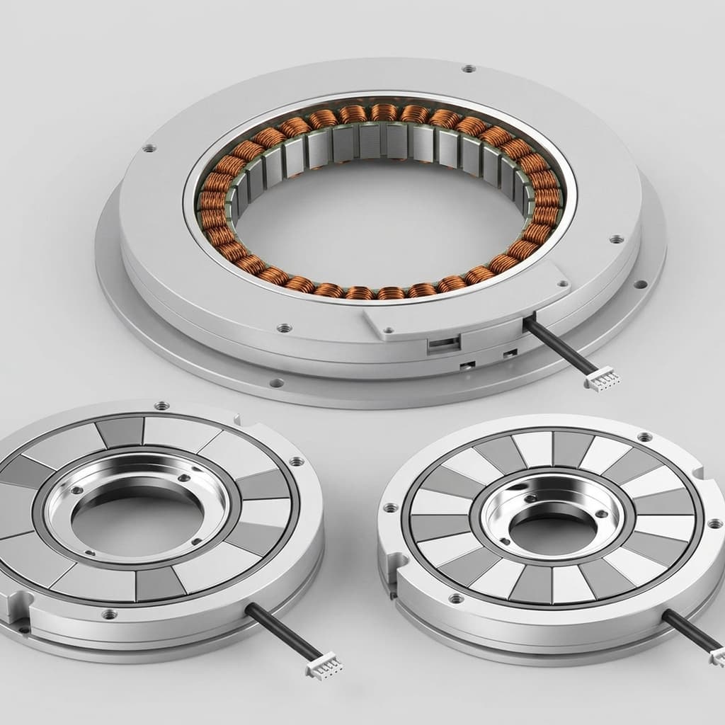
Scope and review date: November 1, 2026; global OEM engineering and procurement guidance for inner-rotor, surface-mounted permanent-magnet (SPM) frameless torque motors. The kit image is illustrative. The diagram and calculations below are screening aids, not measured product results or retention certification. Outer-rotor and buried-magnet designs need different load paths.
For selection, start with rotor radius and speed, shock direction and pulse, rotor temperature history, and the available radial clearance. Then qualify the assembled rotor rather than selecting a sleeve by material name alone. Use the RFQ contact form when you have these inputs ready.
Here N is rpm, omega is rad/s, rho_mag is magnet density in kg/m³, and magnet thickness h_mag and radius are in meters. The pressure expression approximates a thin, uniformly covered magnet ring; segmentation, contact area and edge loading require a more detailed model.
Shock adds directional inertia (F_shock = m_mag * a); tangential acceleration also loads the bond in shear. A radial sleeve does not automatically restrain axial magnet motion or transfer motor torque to the hub.
Conceptual cross-section, not to scale. Adhesive below the magnets and any seating layer below the sleeve are separate interfaces; their dimensions must be identified in the rotor drawing.
r_sleeve is mean sleeve radius, t_sleeve is radial wall thickness, and rho_sleeve is density. This omits interference preload, cure residual stress, thermal mismatch, magnet gaps, local stress concentrations and fatigue. For CFRP, use laminate directional allowables and a suitable failure criterion rather than a metal yield check. Sleeve thickness and preload must be solved together with cold/hot contact pressure.
These are design tendencies, not guaranteed material speed limits, shock ratings or supplier quotations. No architecture has a universal safe rpm or temperature window.
Selection criterion
Structural adhesive only
Metallic can: Inconel / titanium
CFRP sleeve
Radial retention path
Bond and magnet coating carry separation load
Sleeve contains magnets; bond still transfers other loads
Adhesive-only retention can be a candidate when radial space is limited and the assembled joint is validated. Selection needs the actual magnet coating, substrate, bond gap, cure and temperature-dependent properties. Room-temperature cylindrical-joint shear strength cannot establish magnet peel strength or fatigue life.
Do not approve a rotor using a generic 30 m/s or 25g cutoff. Rotor radius, magnet mass, acceleration direction, pulse duration and aged bond performance determine the load case. Secondary radial containment can reduce the consequence of bond failure, while axial restraint needs its own design.
Inconel and titanium sleeves offer different density, alloy strength, electrical resistivity and thermal expansion. Obtain properties for the supplied condition and operating temperature. A thin metallic sleeve can provide radial containment, but does not by itself establish shock survival or cooling capacity.
Conductive sleeves respond to slotting and inverter harmonics as seen in the rotor frame; the synchronous fundamental alone does not describe these losses. The IET sleeve-thickness study examines coupled loss and temperature effects for a specific PMSM. Its results support comparing sleeve and magnet losses together; they do not give a transferable wattage for another motor.
A simple cubic thickness rule is insufficient for a slotted motor with shielding, end effects and changing harmonic fields. Use the actual geometry and inverter spectrum in a validated electromagnetic model.
A hoop-wound CFRP sleeve can reduce rotating mass and sleeve loss relative to some metallic designs. Carbon fibers conduct electricity, however, so CFRP is not loss-free. Fiber type, orientation, resin and contact between fibers affect its electrical and thermal behavior.
Through-thickness heat flow may be much weaker than along the fibers. Check the radial and shaft heat paths together, including contact resistance. Compare calculated magnet temperature against the selected magnet grade's demagnetization limits at the actual magnetic operating point; maximum service temperature is not the Curie temperature.
Thermal expansion mismatch can increase or decrease interface pressure depending on the full hub–magnet–sleeve stack. Check both temperature extremes for contact loss, magnet damage, laminate stress and resin creep. Do not assume that low hoop expansion guarantees thermal-cycle durability.
Hypothetical inputs, not a tested motor: a 68 mm stator bore, 67 mm magnet OD, 3.5 mm magnet radial thickness, 31.75 mm magnet center-of-mass radius, and assumed magnet density of 7,600 kg/m³. The example compares 6,000 rpm operation with a chosen 9,000 rpm calculation point. The 1.5x speed ratio is not a burst-speed claim, a stress safety factor or a prescribed proof test.
At 6,000 rpm the same approximation gives 0.333 MPa. Increasing speed by 1.5x increases this load by 2.25x. Neither value includes shock or thermal preload.
For a 0.35 mm sleeve seated directly on the original magnet OD, mean sleeve radius is 33.675 mm. Using assumed screening densities, not certified material properties:
Screening result at 9,000 rpm
Metallic sleeve, density 8,190 kg/m³
CFRP sleeve, density 1,550 kg/m³
Magnet-pressure contribution
72.18 MPa
72.18 MPa
Sleeve self-stress contribution
8.25 MPa
1.56 MPa
Sum of these contributions
80.43 MPa
73.74 MPa
This calculation isolates density effects; it does not establish allowable stress, safe speed or shock resistance. Strength comparisons need temperature-dependent alloy or laminate allowables, preload, local stress and fatigue analysis. No measured loss, torque constant or rotor temperature is available for this example.
The table assumes no seating layer outside the magnets. The effective non-magnetic separation is approximated as g_eff = running_clearance + sleeve_thickness + outer_seating_layer. A hub-to-magnet adhesive layer is a different interface and is not added to this outer separation.
Radial dimension
Original unsleeved rotor
Add sleeve to original magnets
Redesign to preserve running clearance
Stator bore radius
34.00 mm
34.00 mm
34.00 mm
Magnet outer radius
33.50 mm
33.50 mm
33.15 mm
Sleeve thickness
0 mm
0.35 mm
0.35 mm
Finished rotor outer radius
33.50 mm
33.85 mm
33.50 mm
Running mechanical clearance
0.50 mm
0.15 mm
0.50 mm
Effective outer non-magnetic separation
0.50 mm
0.50 mm
0.85 mm
Decision required
Validate original joint
Check tolerance, runout and hot growth
Recalculate magnet geometry, flux and retention
Engineering consequence: adding a sleeve can consume running clearance; preserving clearance can require a smaller magnet envelope. The redesigned rotor needs a new stress calculation. Neither option supports a fixed percentage torque penalty without a magnetic circuit or field model. Do not grind finished magnets to fit a sleeve without an approved manufacturing process.
Use the following sequence to make the design review and supplier handoff auditable:
Prepare representative surfaces. Agree cleaning and any surface treatment with the magnet/coating and adhesive suppliers. Do not transfer a generic grit-blast specification to a coated magnet.
Control assembly conditions. Record bond gap, sleeve interference, insertion force and temperatures. Any thermal shrink assembly must respect magnet, coating and adhesive limits and avoid condensation. There is no universal heating/freezing recipe.
Record the composite process where applicable. Specify fiber orientation, winding tension, resin batch and cure cycle from a qualified process. Cure alone does not guarantee zero voids.
Define inspection sensitivity. Set allowable defects and the inspection method for the actual laminate or bond; demonstrate that it detects relevant defects in that geometry. Visual inspection alone cannot establish internal bond quality.
Agree balance acceptance.ISO 21940-11:2016 addresses rigid-rotor balancing. Select correction planes and residual-unbalance tolerances for the assembly; a balance grade is not a retention-strength certificate.
Qualify retention separately. Agree thermal-cycle temperatures, dwell, cycle count, shock pulse and axes, vibration spectrum, speed and combined-load sequence. Record specimens and pass/fail criteria, including post-exposure runout, magnet movement, cracks and balance change.
For proof-spin testing, document the applicable standard edition, speed, duration, temperature, containment and sampling plan. Do not turn a generic 1.2x speed / two-minute example into a requirement for every frameless rotor. Production screening and design qualification serve different purposes.
Speed and geometry: continuous, intermittent and fault speeds; duty duration; magnet radius and active length; rotor inertia and acceleration.
Shock and vibration: acceleration, pulse shape/duration, directions, event count, mounting boundary and vibration spectrum. A g-value alone is incomplete.
Temperature and environment: cold start, peak rotor temperature, thermal-cycle dwell/count, humidity and chemical exposure; distinguish rotor from winding temperature.
Retention load paths: radial containment, axial capture, torque transfer, magnet coating and each adhesive interface.
Radial stack: bore, magnet envelope, sleeve and seating layers, tolerances, hot growth, bearing runout and minimum running clearance.
Performance evidence: torque-constant tolerance, total rotor loss and temperature model at the supplied inverter and duty point.
Material/process records: alloy condition or laminate layup, temperature-dependent properties, adhesive cure, inspection and lot traceability.
Send your rotor drawing, speed profile, shock specification and thermal envelope to [email protected], or use the online RFQ form. Ask which retention options and supporting calculations or test records are available for your program; confirm deliverables and timing during the review.
Henkel, LOCTITE 648 TDS (May 2021):Manufacturer technical datasheet. Scope: product-specific cure, joint tests and environmental-performance data; typical data do not certify a coated-magnet assembly.
When is structural adhesive alone sufficient for rotor magnet retention?
Only when the actual magnet coating, bond geometry and aged adhesive joint are qualified for the specified speed, acceleration, shock and rotor temperature. There is no universal 30 m/s or 25g limit. A sleeve can provide radial containment, but axial retention and torque transfer still need separate checks.
Do metallic retaining sleeves always cause more motor loss than CFRP?
Conductive metallic sleeves can generate eddy-current heat under rotor-frame slotting and inverter harmonics. CFRP may reduce that loss, but its conductivity is anisotropic and not zero. Compare total sleeve-plus-magnet loss for the actual winding, inverter and operating point.
What must be checked when a CFRP sleeve undergoes thermal cycling?
Check cold and hot contact pressure, laminate stress, resin temperature limits and radial heat flow. A hoop-wound sleeve can expand differently from the hub and magnets; thermal cycling can change preload or damage interfaces. Validate the actual layup after the required environmental exposure.
How much torque is lost when adding a rotor retention sleeve?
There is no universal percentage. For a non-magnetic sleeve, the radial magnetic separation includes running clearance, sleeve thickness and any layer outside the magnets. Keeping the stator bore and running clearance fixed usually requires a smaller magnet envelope. Recalculate flux and torque constant for the redesigned geometry.
What overspeed test should a buyer specify for magnet retention?
Agree the applicable standard edition, test speed, duration, rotor temperature, sampling plan and acceptance criteria with the supplier. A 1.5x speed screening case is not a stress safety factor or a production proof-test requirement. Balance acceptance does not certify retention strength.
Author
Frameless Torque Motor Engineering Team
Application engineers and manufacturing specialists supporting OEM motion programs.