Cogging Torque vs. Torque Ripple in Direct-Drive Frameless Motors: Slot-Pole Harmonics, Skewing Trade-Offs, and Low-Speed Velocity Jitter Mitigation
Compare cogging torque vs torque ripple in frameless motors. Evaluate slot-pole harmonics, skew losses and low-speed jitter; prepare a measurable OEM RFQ.
Cogging torque vs. torque ripple is a measurement and selection distinction: cogging is magnetic detent torque at zero winding current; energized torque ripple is variation around the operating mean and can contain cogging plus current-dependent disturbances. For a frameless direct drive, specify both quantities, then verify velocity jitter on the assembled axis. A low cogging number alone does not establish tracking accuracy.
Scope and review date: November 5, 2026; global OEM engineering and procurement guidance for slotted, inner-rotor and outer-rotor surface-mounted permanent-magnet (SPM) frameless motors. Slotless motors, strongly salient interior-PM designs and geared-axis dynamics require separate models. Numerical examples below are reproducible screening calculations, not factory test results or product ratings. No clinical, machine-safety or application approval is implied by a motor selection example.
Start with minimum tracking speed, allowable velocity deviation, continuous and peak torque, load inertia, cooling and available servo drive. Review our Frameless Torque Motors range, or send these requirements through the engineering RFQ contact form to discuss the evidence needed for a candidate kit.
Cogging torque (T_cog) comes from the changing interaction of rotor permanent magnets with the stator's slotted iron geometry. It exists with the windings open-circuit and the inverter disconnected. Its torque-versus-angle waveform is approximately repeatable over a mechanical revolution, although assembly errors can introduce additional orders. In an ideal conservative model its average over a full revolution is zero.
An unpowered hand-rotation check can reveal detents, but it also includes seal friction, bearing drag and fixture effects. It cannot establish a small peak-to-peak acceptance limit. A shaft that feels smooth is not a measurement report, and a noisy trace is not necessarily magnetic cogging.
Here theta_m is mechanical angle, theta_e is electrical angle and p is pole pairs. T_harm represents flux and current harmonic interactions; T_reluct captures saliency-related variation; T_inv represents inverter and current-control errors. Under saturation these contributions interact, so this is a diagnostic breakdown rather than an exact linear separation at every load.
For a balanced three-phase system, fifth and seventh back-EMF harmonics interacting with fundamental current can produce sixth electrical-order torque ripple. Current sensor offsets, dead time and commutation errors can add other orders. Measure at the intended torque and speed rather than extrapolating from an unpowered cogging test.
Define energized peak-to-peak ripple as 100 * (T_max - T_min) / abs(T_avg) only when the mean torque is meaningfully nonzero. Near zero mean torque, report the absolute disturbance in N·m; the percentage becomes unstable or undefined. Also state measurement bandwidth, filtering, current convention and whether the reported torque is electromagnetic or shaft torque.
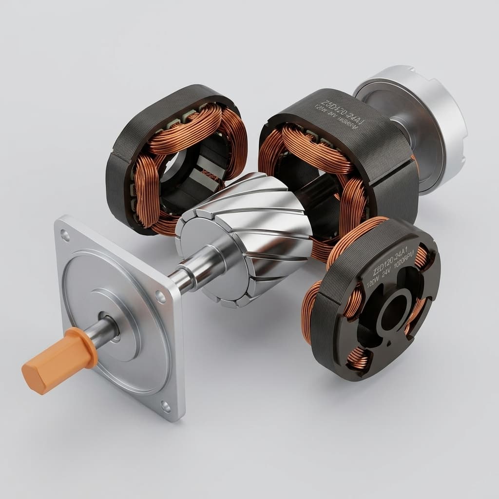
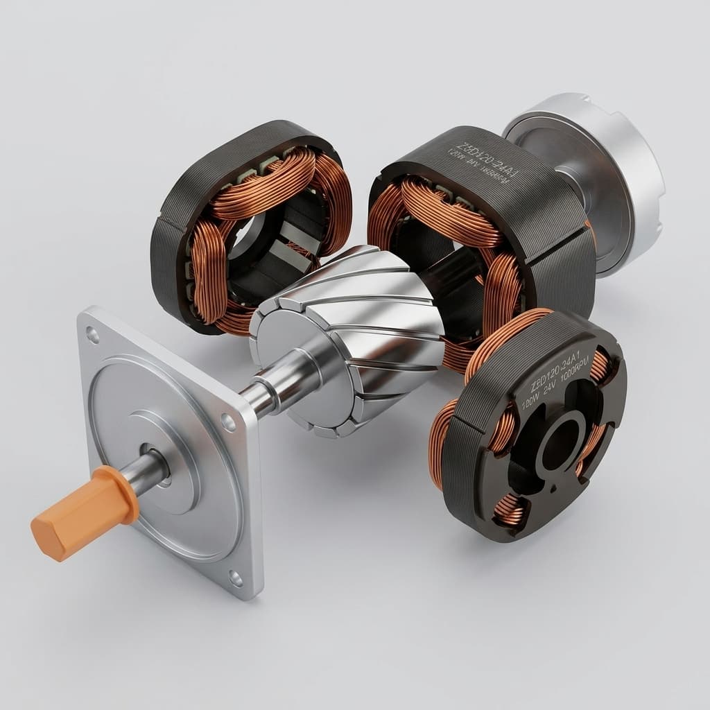
Representative assembly illustration. The image does not verify a particular skew arrangement, manufactured motor or measured reduction in cogging.
The following diagram separates disturbance sources conceptually. Its waveforms have arbitrary amplitudes and do not predict velocity jitter or a compensation percentage.
For an ideally symmetric slotted permanent-magnet machine, the basic cogging spatial order is the least common multiple of stator slots S and magnetic poles 2p:
N_c = LCM(S, 2p) [cycles / mechanical revolution]f_cog = N_c * n / 60 [Hz, with speed n in rpm]q = S / (3 * 2p) [slots / pole / phase, three phases]
A particular harmonic can cancel through geometry or skew, and manufacturing errors can create lower orders absent from the ideal model. Therefore N_c describes symmetry, not a guarantee that the largest measured spectral peak occurs there.
Zhu and Howe's design-parameter study examines how slot/pole combinations interact with magnet arc, skew and slot geometry. Its conclusions are design-dependent: increasing LCM alone does not establish a universal inverse-amplitude law. Compare candidates with consistent geometry, excitation and manufacturing assumptions.
The following values are calculated directly from integer slot and pole counts. They identify orders and electrical frequency; they do not rank suppliers or establish winding factors. A winding factor also needs the coil layout, pitch and connection, which cannot be recovered uniquely from slot and pole counts alone.
Stator slots S
Rotor poles 2p
q, three phases
N_c = LCM(S, 2p)
Basic cogging pitch, mechanical degrees
Electrical Hz at 60 rpm
12
8
1/2
24
15.000
4
12
10
2/5
60
6.000
5
12
14
2/7
84
4.286
7
18
16
3/8
144
2.500
8
24
20
2/5
120
3.000
10
24
22
4/11
264
1.364
11
24
28
2/7
168
2.143
14
36
32
3/8
288
1.250
16
36
42
2/7
252
1.429
21
48
44
4/11
528
0.682
22
Fractional-slot concentrated windings can shorten end turns and support compact stator construction. Their space harmonics can also increase rotor losses or force harmonics, depending on the winding and magnetic circuit. A 12-slot/10-pole design is consequently a candidate architecture, not an automatic low-jitter approval. Request the winding factor, torque constant, rotor losses and force spectrum for the actual winding.
For procurement, compare absolute cogging torque and on-load ripple at the same temperatures and operating points. A high-pole-count design may shift a disturbance to higher temporal frequency at a given speed, affecting compensation bandwidth and structural response. It still needs assembled-axis validation.
Hardware mitigation changes selected magnetic harmonics before the controller acts. Bianchi and Bolognani discuss several reduction techniques and their effect on back-EMF. Their work supports evaluating the complete electromagnetic trade-off, rather than treating a cogging reduction technique as universally beneficial.
The magnet arc ratio is magnet circumferential width divided by pole pitch. Changing this ratio, profiling magnet edges or narrowing slot openings can reduce particular harmonics. There is no universal optimum arc ratio or guaranteed reduction percentage for all frameless kits. Air gap, magnet thickness, tooth shape and saturation change the result; tolerances may weaken an ideal cancellation.
Ask the supplier for a parameter sweep that reports both cogging and useful torque. A plot with a very sharp minimum can signal sensitivity to magnet placement or slot-opening tolerances. Include the effects of the assembled air gap and any retention sleeve before accepting the nominal optimum.
Use the limiting value 1 at zero skew. A full cogging-period skew, beta = 2*pi/N_c, cancels that harmonic in this simplified model. A full slot pitch is a different angle and can impose a much larger fundamental penalty. End effects, saturation and axial leakage require more detailed analysis.
For example, with 12 slots and 10 poles, p = 5 and N_c = 60. A 6-degree continuous mechanical skew gives a fundamental factor of approximately 0.9886. A 30-degree slot-pitch skew gives approximately 0.7379. These are ideal averaging calculations, not measured torque constants. They show why specifying only “skewed rotor” is inadequate.
If the actual torque constant changes by a factor k, then at equal output torque and unchanged resistance:
An assumed k = 0.95 increases required current by 5.3% and winding copper loss by 10.8%. This comparison holds winding temperature, resistance and current convention fixed. It does not establish total motor loss, inverter loss or continuous torque after thermal equilibrium.
For equal axial segments at mechanical angles theta_j, the ideal harmonic averaging factor is the magnitude of sum(exp(i*h*theta_j))/M, where M is the number of segments. Offsets theta_j = j*2*pi/(h*M) cancel the chosen order in an equal-weight ideal model. Adjacent segments differ by 180 electrical phase degrees for that harmonic only when M = 2; three steps use 120 degrees.
Discrete skew may simplify some assembly operations while adding magnet pieces, placement tolerances and axial interfaces. Continuous or asymmetric skew can create axial magnetic forces. Do not size bearings with a helical screw analogy or assume a symmetric arrangement guarantees zero thrust: obtain three-dimensional force results for the actual rotor, end geometry and operating currents.
Mitigation architecture
Intended effect
Main trade-off
Evidence to request
Slot/pole and winding selection
Change allowed harmonic orders
Space harmonics, losses and winding factor
Winding layout and torque/force spectra
Magnet arc optimization
Reduce selected slotting interactions
Useful flux and tolerance sensitivity
Geometry sweep and tolerance analysis
Magnet edge profiling
Shape air-gap flux
Magnet tooling and local gap changes
Back-EMF, cogging and torque comparison
Continuous stator skew
Average spatial harmonics axially
Fundamental flux reduction and stack production
Actual skew angle, torque constant and axial forces
A lookup table or harmonic feedforward command can counter a repeatable angle-dependent disturbance. First distinguish it from ordinary feedback tuning: feedback reacts to error, whereas feedforward applies a learned command at a registered rotor angle. Either method needs adequate current headroom and a stable mechanical system.
A practical mapping cycle records low-speed motion in both directions, with repeat runs to distinguish magnetic features from friction, cables and external load. An assembled-axis map can include those external disturbances; it should not then be advertised as the motor's intrinsic cogging profile. Retain calibration temperature, encoder zero, load state and firmware version.
For mechanical-angle indexing, one possible representation is:
i_q,comp(theta_m) = sum_h [I_h * sin(h * theta_m + phi_h)]f_dist = h * n / 60
Do not mix mechanical order h with electrical order without the pole-pair conversion. At N_c = 120 and 300 rpm, the basic cogging disturbance occurs at 600 Hz. That arithmetic alone says nothing about the attainable attenuation.
PWM switching frequency, current-loop update rate and closed-loop current bandwidth are different quantities. Delays, voltage saturation, filters and mechanical resonances affect the useful compensation range. Ask for the current-command-to-current frequency response, and assess the complete torque-to-velocity response of the axis.
For an illustrative first-order current response H(f) = 1/(1 + i*f/f_bw), a 600 Hz command with f_bw = 1500 Hz has magnitude 0.928 and phase lag 21.8 degrees. It does not inherently imply the 45–90 degree lag sometimes assumed from frequency alone. With an otherwise perfect inverse torque map and no phase correction, the residual disturbance ratio in this simplified example is abs(1-H) = 0.371.
Using a disturbance frequency below one tenth of measured bandwidth is a conservative initial screening choice, not a universal pass criterion. Validate attenuation, current peaks and stability at each operating region. Gain scheduling or phase correction may be appropriate; neither a fixed rpm cutoff nor an arbitrary “forbidden” bandwidth fraction applies to every drive.
If your team already has angle-indexed torque or velocity logs, include them in the custom motor engineering request. They help determine whether geometry, mounting, encoder registration or drive behavior deserves the next investigation.
This is a hypothetical rigid-inertia screening example, not a customer case study. Assume a 6.2 N·m continuous-torque candidate, total motor-plus-load inertia J = 0.025 kg·m², mean speed n = 2 rpm, and one sinusoidal disturbance with peak amplitude A = 0.001 N·m. No actual motor geometry, cogging amplitude or controller performance is inferred from these inputs.
Ignoring feedback, damping, friction and compliance, integrate J*d(Delta omega)/dt = A*sin(2*pi*f*t) to obtain:
The table deliberately holds amplitude constant to isolate the effect of disturbance order. Higher slot/pole LCM does not guarantee the same or a lower amplitude in a physical motor.
Assumed mechanical order h
Frequency at 2 rpm, Hz
Assumed peak torque, mN·m
Calculated peak speed deviation, % of mean
24
0.8
1.0
3.800
60
2.0
1.0
1.520
84
2.8
1.0
1.086
120
4.0
1.0
0.760
144
4.8
1.0
0.633
168
5.6
1.0
0.543
264
8.8
1.0
0.345
528
17.6
1.0
0.173
For the 60th-order example, mean speed is 0.20944 rad/s and calculated peak deviation is 0.003183 rad/s. If the target were ±1% of mean speed, this inertial model would allow approximately 0.658 mN·m peak at 2 Hz. For a single symmetric sinusoid that is 1.316 mN·m peak-to-peak, or about 0.0212% of the assumed 6.2 N·m reference torque.
These values are not a recommended universal cogging specification. Real feedback can reject low-frequency disturbances, while compliance or resonances can amplify particular orders. At other speeds, the same order moves to a different frequency. Multiple harmonics also combine with different phases, so one peak-to-peak number cannot reconstruct the velocity waveform.
For a defensible axis prediction, replace the rigid-inertia response with the measured closed-loop transfer function from disturbance torque to velocity. Evaluate encoder filtering and sample rate as well: a heavily filtered speed trace can hide the very ripple being specified. Acceptance belongs to the assembled axis at the agreed load, speed and temperature.
IEEE Std 1812-2023 is a guide for testing permanent-magnet machines and supersedes the 2014 trial-use edition. Its public scope does not impose a particular test or guarantee performance. The following is a proposed engineering test plan, not a reproduction of a verified standard clause. Agree the applicable edition, contractual limits and detailed procedure with the supplier.
Define the mechanical fixture and conditions. Record whether the test concerns the bare kit in a reference fixture or the final customer assembly. Document air gap, alignment, bearings, seals, temperature and torque-sensor calibration. A change in mounting can change the result and its uncertainty.
Isolate the winding terminals. Disconnect the inverter and leave phases open-circuit. Shorted phases or conducting inverter paths can add electromagnetic braking. Confirm isolation before backdriving the motor.
Select speed and angular sampling from the measurement need. A low-speed trial, for example 1 rpm, is a starting point to validate, not a standard-mandated value. Repeat at another sufficiently low speed to assess drag and dynamic effects. If the highest analyzed mechanical order is h_max, the theoretical angular Nyquist requirement is more than 2*h_max samples per revolution; use additional samples and appropriate anti-aliasing for amplitude accuracy. Encoder nominal bit count alone does not establish angle accuracy or torque resolution.
Record aligned sweeps in both directions. Convert sensor outputs to the same physical torque sign and mechanical-angle coordinate before comparing them. Resample to common angle positions; reversing the array without angle registration can create a false cancellation.
Report waveform, spectrum and uncertainty. Deliver raw signed torque-versus-angle data, repeated-sweep variation, peak-to-peak value, filtering, sensor range and uncertainty at the specified limit. A nominal accuracy percentage of sensor full scale may be inadequate for a small cogging signal.
Here the traces are already transformed into the same magnetic-torque reporting convention. Averaging removes only the modeled direction-odd term; hysteresis, unequal friction, temperature drift and fixture errors can remain. Do not subtract traces while simultaneously treating both as signed measurements in the same coordinate: that extracts the direction-odd component rather than the conservative cogging term. Verify polarity with a known applied torque.
For energized ripple, use a separate controlled-load test at specified torque, speed, winding temperature and drive settings. Include PWM frequency, current-loop configuration, compensation status and acquisition bandwidth. A mechanical torque transducer may not capture high-frequency electromagnetic torque without a characterized fixture transfer function. Assess the agreed acceptance band rather than treating every spectral component as equally measurable.
For both tests, specify T_pk-pk = T_max - T_min over a defined number of mechanical revolutions. If acceptance includes an uncertainty allowance, write the decision rule into the purchase specification so buyer and supplier reach the same result from the same data.
Yes. Slot opening changes air-gap permeance and can alter the cogging spectrum. Its effect depends on gap length, tooth geometry and magnet layout, so a width in millimeters is not a transferable design rule. Compare candidate geometries with consistent dimensions and ask how insertion, insulation and manufacturing constraints affect the proposed slot opening.
Eccentricity and unequal magnet placement break ideal symmetry and can add low mechanical orders, force imbalance and bearing reactions. A new low-order peak is a diagnostic clue rather than proof of one specific fault. Check alignment and runout alongside the spectrum; use our air-gap eccentricity and UMP guide to structure the mounting discussion.
Only for a symmetric waveform about its reference mean. A symmetric signal ranging from -50 to +50 mN·m is 50 mN·m peak and 100 mN·m peak-to-peak. Real waveforms can be asymmetric. Request maximum, minimum, mean and the raw trace instead of automatically multiplying every vendor's “peak” figure by two.
There is no universal percentage. The reference continuous torque, disturbance orders, minimum speed, inertia, friction, encoder and controller all matter. Use the worked example to understand frequency dependence, then validate the complete axis. A small percentage of a large rated torque can still be a significant absolute disturbance on a lightly loaded mechanism.
Saturation changes flux linkage, incremental inductance and harmonic interactions. Its effect depends on current, rotor angle, temperature and magnetic design. Request energized measurements at the required continuous and peak operating points, with peak duration and cooling stated; do not infer a fixed ripple multiplier from peak current alone.
A sleeve or other layer outside the magnets changes the magnetic separation if the surrounding geometry is held fixed, and conductive materials can add losses. Re-evaluate torque constant, harmonic spectrum and thermal behavior after retention changes. Our rotor magnet retention guide covers the associated mechanical questions; adhesive or sleeve selection does not follow from a cogging number alone.
Send your envelope drawing, torque-speed duty cycle, inertia, temperature range, drive details and allowable velocity deviation to [email protected] or the RFQ contact form. These inputs support a candidate review and proposed validation plan; final performance requires an agreed prototype and acceptance test.
Reviewed November 5, 2026. These primary references support the design principles and standards scope. The worked arithmetic, RFQ checklist and proposed acceptance plan are this article's engineering synthesis; they are not measured product results or quoted standard requirements.
Zhu, Z. Q., and Howe, D. (2000):Influence of design parameters on cogging torque in permanent magnet machines. IEEE Transactions on Energy Conversion, 15(4), 407–412. DOI: 10.1109/60.900501. University of Sheffield repository record; examines slot/pole combinations, magnet arc, skew and geometry dependence. Conclusions from one geometry are not universal production limits.
Bianchi, N., and Bolognani, S. (2002):Design techniques for reducing the cogging torque in surface-mounted PM motors. IEEE Transactions on Industry Applications, 38(5), 1259–1265. DOI: 10.1109/TIA.2002.802989. University of Padua record and abstract; identifies reduction techniques and back-EMF trade-offs without establishing the numerical performance of our products.
IEEE Std 1812-2023:IEEE Guide for Testing Permanent Magnet Machines. Official scope and edition status; supersedes 1812-2014. The public summary establishes general applicability, not the detailed numeric test conditions proposed in this guide. Consult the applicable full edition when specifying compliance.
What is the primary physical difference between cogging torque and torque ripple?
Cogging torque is position-dependent magnetic detent torque present with zero winding current in a slotted permanent-magnet motor. Energized torque ripple is periodic variation around the mean operating torque and can include cogging, back-EMF harmonics, saturation and current-control errors. Specify and measure the two quantities separately.
Why does cogging torque matter far more in frameless direct drives than in geared servo motors?
A direct drive couples motor disturbances directly to the payload, so low-speed smoothness depends on motor torque quality and the assembled servo system. An ideal N:1 reducer multiplies motor torque, including its disturbance component, by N at the output. Its inertia, compliance, friction and controller change the resulting motion response; a gear ratio does not simply divide output cogging torque by N.
How does the slot-pole combination dictate intrinsic cogging torque frequency and amplitude?
For an ideally symmetric slotted motor, the basic cogging order is N_c = LCM(S, 2p) cycles per mechanical revolution. This identifies possible harmonic orders, not an amplitude guarantee. Magnet geometry, slot openings, air gap, skew and manufacturing errors determine the actual spectrum. Request calculated and measured torque-versus-angle data for the proposed design.
What engineering trade-offs occur when applying rotor magnet skewing or stator slot skewing?
Skew averages selected spatial harmonics but can reduce torque constant and increase current and copper loss at the same output torque. For ideal continuous mechanical skew beta, the fundamental skew factor is sin(p*beta/2)/(p*beta/2), where p is pole pairs. Discrete step-skew needs a segment phasor calculation. Reduction percentages and axial forces require design-specific analysis and testing.
Can drive-side software compensation eliminate the need for low-cogging motor hardware?
Position-indexed feedforward can reduce repeatable disturbances when calibration, encoder registration, current headroom and current-loop response are adequate. A harmonic of mechanical order h occurs at h*n/60 Hz for speed n in rpm. Validate compensation across the actual speed and temperature range; there is no universal rpm cutoff or guaranteed jitter reduction.
How should an OEM specify cogging torque and torque ripple limits in a commercial RFQ?
Specify unpowered cogging in N*m peak-to-peak, its reference torque if expressed as a percentage, temperature, fixture, speed, angular sampling and uncertainty. Specify energized ripple at defined torque, speed, drive settings and measurement bandwidth. Agree the test plan and applicable standard edition with the supplier; a standards citation alone does not establish an acceptance limit.
Author
Frameless Torque Motor Engineering Team
Application engineers and manufacturing specialists supporting OEM motion programs.