Frameless Torque Motor Ring Encoder Integration: Optical vs. Magnetic vs. Inductive Feedback, Runout Budgets, Stray-Flux Shielding, and Commutation Alignment
Compare frameless torque motor ring encoders, calculate runout error, validate stray-flux shielding, and define commutation alignment. Plan an engineering RFQ.
Frameless torque motor ring encoder integration starts with the installed error budget, the required clear bore, and the drive's startup behavior. Choose optical feedback when fine angular metrology and a protected optical path dominate; compare magnetic feedback for compact packaging and cost; consider inductive feedback when contamination resistance and an annular sensing geometry matter. Then verify the selected model in the actual motor assembly. Sensing technology alone does not establish accuracy, field immunity, or an acceptable working gap.
Scope and review date: November 8, 2026; global engineering and procurement guidance for OEM direct-drive rotary stages, robot joints, and pointing axes. The worked examples are calculations, not measured hardware results or product guarantees. Geared joints are discussed only where compliance affects feedback placement. This guide does not qualify a medical, aerospace, or safety function.
Start by specifying the hollow through-bore, installed angular accuracy, repeatability, low-speed velocity ripple, temperature range, and servo interface. Review our Frameless Torque Motors and Compact Robot Joint Motors, or send your envelope through the engineering RFQ contact form for a packaging review.
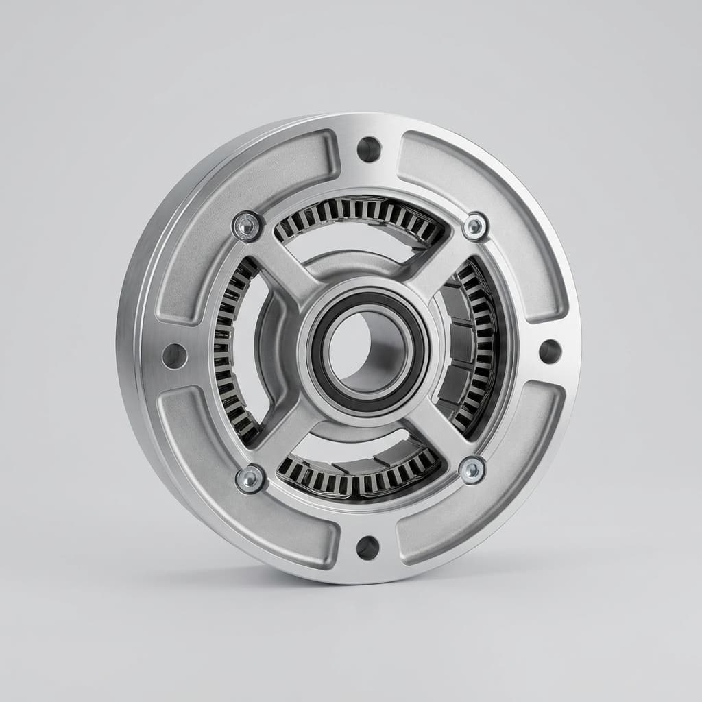
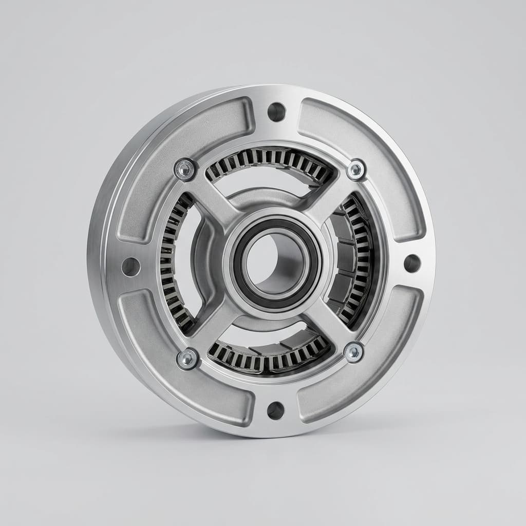
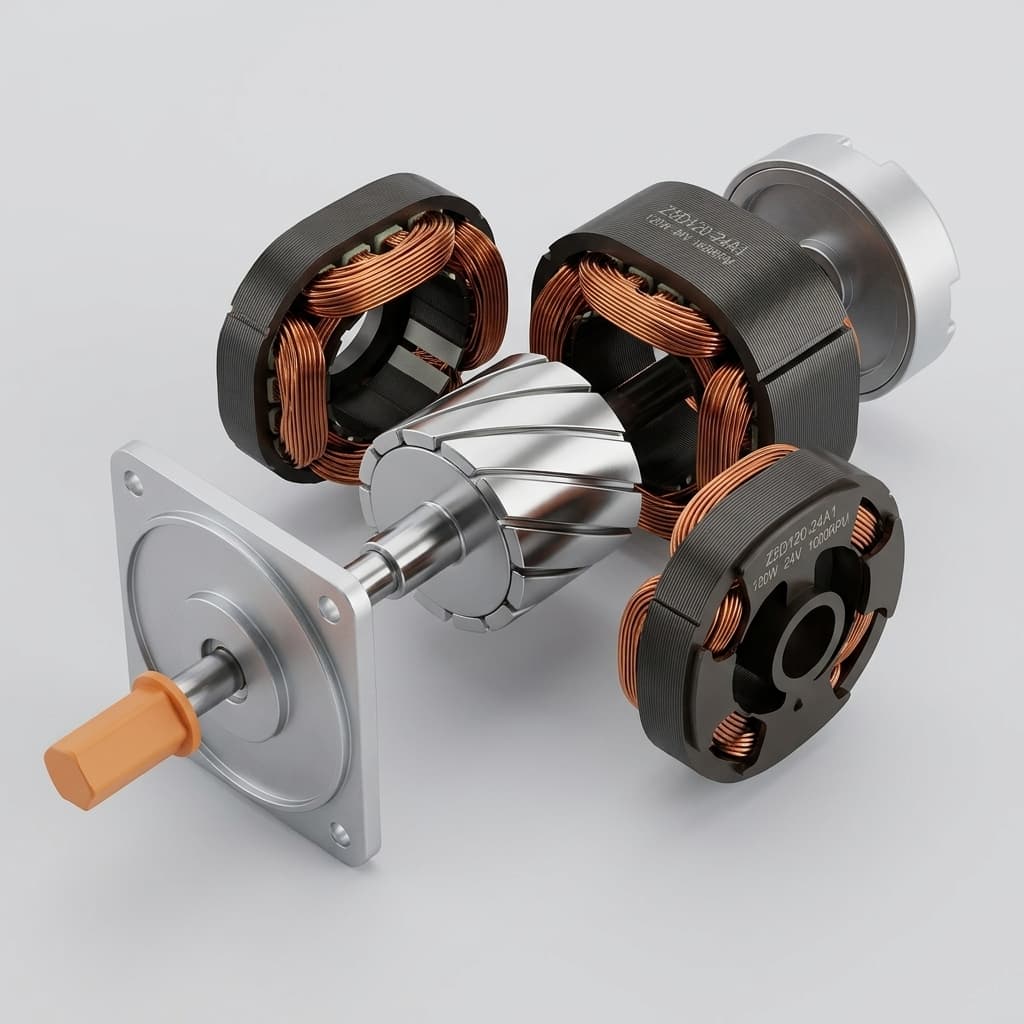
Representative motor rendering. This image illustrates an annular package; it is not evidence of a supplied encoder, shielding design, or tested integration. The schematic below separates the feedback components.
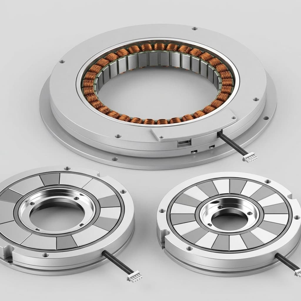
A frameless motor is supplied as an unhoused stator and rotor electromagnetic kit. The integrator usually provides the bearings, rotor carrier, housing, and position feedback. A ring encoder preserves a clear central passage for cables, optics, pneumatic lines, or slip rings while placing the scale close to the rotating payload.
Ring feedback is a practical choice, rather than a requirement for every frameless motor. A design with an available shaft extension can use a conventional encoder, and some applications use a resolver or another feedback arrangement. The packaging decision follows the application's aperture and stiffness requirements.
Direct coupling removes transmission backlash but retains bearing deflection, structural compliance, thermal movement, and measurement error. Separate three requirements in the RFQ: absolute angular accuracy, repeated positioning at the same location, and smooth motion at the specified speed. One headline bit count cannot describe all three.
For a permanent-magnet synchronous motor with P pole pairs, electrical angle follows theta_e = P × theta_m + offset, modulo one electrical revolution. A 40-pole motor has 20 pole pairs, so a 0.5-degree mechanical offset becomes a 10-degree electrical offset.
In a simplified surface-PM model with negligible saliency, fixed stator current, and no field weakening, useful torque scales with cos(delta_e). A constant 10-degree electrical error therefore reduces torque by about 1.52% at the same current. Copper loss is unchanged at fixed current. Maintaining the original torque requires approximately 1 / cos(10°) times the current, increasing copper loss by about 3.11%, assuming unchanged resistance.
A constant angle offset does not by itself prove cyclic torque ripple. Position-dependent encoder errors, phase imbalance, cogging, and control dynamics can create ripple, and should be evaluated separately. Define both the allowed electrical offset and the installed cyclic error instead of treating a calibration number as the complete feedback specification.
Use this matrix to shortlist architectures. Entries describe selection questions and common trade-offs, not universal performance bands. Obtain accuracy, gap, environmental, and interface limits for the exact ring size and readhead combination before releasing CAD.
Engineering Parameter
Optical Ring Encoders
Magnetic Ring Encoders
Inductive Ring Encoders
Sensing principle
Light reads a graduated ring or disc
A sensor reads a magnetized ring
Excited coils detect a conductive or patterned target; implementation varies
Accuracy selection
Often shortlisted for fine angular metrology; verify installed error
Compare calibrated system accuracy for the selected ring
Check specified accuracy over gap, tilt, and temperature
Resolution and cyclic error
Readhead interpolation and scale quality matter
Magnetic pattern and processing affect cyclic error
Coil/target geometry and processing affect cyclic error
Radial eccentricity
Single-head arrangements need a centering budget
Mounting error and calibration remain important
Distributed sensing can reduce sensitivity in some designs
Axial gap
Use the readhead's ride-height and tilt limits
Use the specified ring/readhead gap window
Use the model's gap window; do not assume it is always tighter
Motor magnetic fields
Optical sensing avoids magnetic-scale interaction; electronics still need EMC checks
Field immunity varies substantially by sensor design
Does not read a permanent magnetic scale; validate motor/PWM interference
Dust, oil, and moisture
Contamination can obstruct the optical path
Contamination tolerance does not imply an IP rating
Contamination resistance depends on construction and sealing
Nearby materials
Preserve optical clearance and scale mounting conditions
Ferromagnetic structures can change the working field
Conductive or magnetic structures can affect coupling
Mechanical packaging
Allow readhead adjustment and scale protection
Low-profile rings can suit compact joints
Annular PCB assemblies can suit shallow packages
Installed cost
Include metrology, cleanliness, and alignment labor
Include calibration and any required field mitigation
Include target mounting, gap control, and qualification labor
Optical selection: shortlist optical feedback when angular metrology or very smooth scanning dominates, and the housing can protect the sensing path. Specify allowable installed error and cyclic error separately. An enclosure IP rating alone does not ensure the internal scale remains clean during assembly or service.
Magnetic selection: shortlist magnetic feedback for compact joints and cost-sensitive industrial designs, then check the actual immunity limits. For a concrete example, RLS AksIM-2 lists resolution up to 20 bits and calibrated accuracy from ±14 to ±72 arcseconds across configurations, together with external-field immunity. These are model-specific claims, not a rating for all magnetic encoders or every motor installation.
Inductive selection: consider inductive feedback when optical contamination is difficult to control and the target geometry fits the package. Inductive designs generally use AC excitation and a passive target, but coil geometry, electronics, nearby metal, and operating frequency vary. Do not group capacitive/electric-field encoders into the inductive category simply because both use PCB structures. Request the selected inductive encoder's installation drawing and interference limits rather than transferring numbers from another sensing family.
Motor permanent magnets and phase currents produce fields near the feedback assembly. The field at the readhead depends on the rotor geometry, pole pattern, back iron, axial position, and current. Magnet remanence is not the field measured at the encoder.
There is no universal safe separation of 25 mm, no universal magnetic-sensor saturation threshold, and no shield thickness that guarantees immunity. A simple inverse-cube dipole approximation can describe a distant isolated source; it is not a reliable near-field model for a multipole rotor and surrounding steel structure.
Obtain the encoder limits. Ask for permissible external field magnitude, direction, gradient, and frequency, plus the installation conditions behind any immunity claim. If these limits are unavailable, retain the field-compatibility decision as unresolved.
Map the proposed sensor location. Measure the field vector at the readhead position throughout one mechanical revolution. Record the probe location and orientation. Repeat relevant conditions with motor current applied using an approved fixture; static measurements alone do not characterize PWM interference.
Measure feedback error. Compare reported angle with an independent reference during slow rotation, holding, and acceleration. Log position error, signal-quality indicators, communication errors, and drive faults under the required current and temperature conditions.
Evaluate mitigation. Compare increased separation, a different sensing architecture, a different readhead, or a designed magnetic shunt. Repeat the same acceptance measurements after changes.
A high-permeability steel or nickel-iron barrier can redirect flux, but performance depends on its complete geometry, saturation margin, mechanical processing, and magnetic return path. It can also alter the encoder's own field or the motor magnetic circuit. Aluminum or polymer spacers provide separation; they do not provide static magnetic shielding merely by being nonmagnetic. A conductive shield may help at higher frequencies, subject to its geometry and grounding.
Keep motor power conductors and sensitive feedback wiring arranged according to the drive and encoder manuals. Differential signaling, cable shields, connector bonding, and supply integrity address electrical interference; they do not replace a magnetic compatibility check.
A modular encoder measures relative motion between its readhead and scale. Both mounting structures belong in the budget. Inspect the scale's actual reference features and the bearing axis rather than relying solely on a housing diameter tolerance.
For a single localized readhead, a circular scale with a small center offset e and pitch radius R has a first-order peak angular error:
Peak angular error ≈ e / R radiansPeak angular error ≈ 206,265 × e / R arcseconds
Use the same length units for e and R. For pure eccentricity of a round reference surface, e = TIR / 2, where TIR is total indicated runout. Form error, bearing motion, probe setup, and a reference surface that is not concentric with the graduation track can invalidate that shortcut. The estimate is not a universal error model for distributed multi-sensor encoders.
Worked screening example: a 100 mm pitch-diameter ring has R = 50 mm. An eccentricity of 0.025 mm, corresponding to 0.050 mm TIR under the assumptions above, produces 206,265 × 0.025 / 50 = 103.13 arcseconds peak error. A 20-bit word resolves approximately 1,296,000 / 2^20 = 1.236 arcseconds per count. The eccentricity contribution is about 83 times one count; high resolution has not removed installation error.
The following values are calculated for e = 0.010 mm, equivalent to 0.020 mm TIR from pure eccentricity:
Scale Pitch Diameter
Pitch Radius
Calculated Peak Error
40 mm
20 mm
103.13 arcseconds
60 mm
30 mm
68.76 arcseconds
80 mm
40 mm
51.57 arcseconds
100 mm
50 mm
41.25 arcseconds
150 mm
75 mm
27.50 arcseconds
200 mm
100 mm
20.63 arcseconds
For an allocated eccentricity contribution of 10 arcseconds at R = 50 mm, the same model gives e ≤ 0.00242 mm, or approximately 0.00485 mm TIR. Other errors still need their own allocations. Add worst-case bounds conservatively unless independence and statistical assumptions justify another method.
Two opposed readheads can cancel first-harmonic eccentricity in an ideal matched arrangement. Convert both readings to the same angular reference, account for their physical separation and scale coding, synchronize sampling, and unwrap the angles before averaging. A naive average of 359 degrees and 1 degree gives 180 degrees rather than the intended zero crossing.
Residual errors include unequal readhead behavior, imperfect spacing, even spatial harmonics, calibration drift, and structural movement. Do not assume a second head guarantees sub-5-arcsecond accuracy or removes physical payload translation. Renishaw's rotary-encoder accuracy paper discusses installed error and multiple-readhead compensation; validate the complete assembly against the application's measurement reference.
Build the gap stack from assembly tolerance, bearing axial displacement, carrier deflection, scale tilt, and differential thermal growth. Use the gap limits from the selected encoder, regardless of sensing technology.
For an illustrative aluminum housing and steel hub, each with a 50 mm effective axial length and the same 55 K temperature rise, use approximate coefficients of 23 × 10^-6/K and 12 × 10^-6/K. Aluminum growth is 0.06325 mm; steel growth is 0.03300 mm. Differential growth is therefore 0.03025 mm. Whether it opens or closes the gap depends on the mounting geometry. Actual components may have different temperatures and constrained expansion, so this estimate is only a screening calculation.
Select bearing stiffness, preload, life, and friction for the load case. Crossed-roller or duplex angular-contact arrangements are candidates, not mandatory solutions. Measure relative ring/readhead movement under the actual axial and moment loads before accepting the gap margin.
If the calculated tolerance leaves no practical assembly margin, send the stack-up and error allocations through our engineering contact form before freezing the carrier drawing.
This conceptual schematic identifies the scale, readheads, carrier, and possible flux barrier. It is not to scale and does not prescribe a motor air gap, spacer dimension, shield, loop bandwidth, or qualified assembly. Dual readheads are optional; the layout must follow the selected encoder's installation requirements.
An absolute encoder reports a mechanical position; it does not automatically know the rotor's magnetic angle. Verify pole-pair count, phase sequence, encoder direction, and the drive's angle convention before setting the commutation offset. Replacing the rotor, moving the ring, or changing phase wiring can invalidate a stored calibration.
Use the servo manufacturer's supported alignment routine with its specified current, timing, and permitted motion. The drive creates a stationary current vector, allows the rotor to settle, and records the encoder angle. Friction, payload torque, or a brake can prevent alignment and create a misleading offset. Repeating the routine from multiple allowed starting positions helps reveal this problem.
The drive controls all three phases electronically. Do not physically tie phase outputs together based on a conceptual current-vector description. The permissible alignment current is motor- and drive-specific; a fixed percentage of continuous current is not a universal commissioning setting.
For an illustrative convention with positive encoder direction and a zero-angle stator vector, convert a raw count c into mechanical degrees first:
N = counts per mechanical revolutionP = motor pole-pair countmechanical angle = 360 × c / Nstored offset = (P × mechanical angle at alignment) mod 360electrical angle = (P × mechanical angle - stored offset) mod 360
For N = 1,048,576, P = 20, and an aligned count of c = 65,536, mechanical angle is 22.5 degrees and stored offset is 90 electrical degrees under this convention. A drive using the opposite sign or another reference vector needs its own documented calculation. Store and retrieve the parameter using the supported drive procedure.
DC alignment permits rotor motion, potentially up to half an electrical revolution under ideal unloaded conditions. It is unsuitable where that movement cannot be accommodated. An absolute encoder with a previously validated offset can support startup without a new movement routine, provided the mechanical relationship remains intact.
An external backdrive fixture can compare generated voltage with encoder position. Specify rotation direction, speed, winding phase sequence, voltage reference, and the expected angle relationship. Use appropriate differential measurement equipment and the motor/drive isolation procedure.
Line-to-line voltage and phase-to-neutral voltage are not interchangeable references: balanced sinusoidal signals have a 30-electrical-degree phase difference between them, with sign determined by the chosen phase order. An index pulse occurs at a chosen mechanical reference, not necessarily the required electrical zero. Do not rotate the ring until the pulse and any convenient voltage crossing coincide.
At constant mechanical speed, a measured timing difference converts to electrical angle through delta_e = P × omega_m × delta_t, using radians and seconds consistently. Apply the known reference-phase correction and the drive's convention. Store the result in the drive unless the selected encoder explicitly supports the required writable offset; BiSS or EnDat connectivity alone does not guarantee that register exists.
Some drives estimate magnetic orientation from an injected signal and the motor's differential inductance. Success depends on the motor, current level, saliency, noise, and the drive algorithm. Surface-PM motors may offer little usable saliency, and axis detection can have a 180-degree electrical polarity ambiguity unless the method resolves it.
There is no universal saliency ratio, injection frequency, or voltage that qualifies this approach. Treat HFI as an option requiring explicit support and motor-specific validation, rather than a default substitute for a known absolute angle on a motion-restricted axis.
A pin, key, or optical fiducial can make assembly repeatable, but the supplier must establish its relationship to the magnetic poles. Rotor magnet placement, ring mounting, and carrier tolerances remain part of the offset budget. Retention hardware must follow the encoder supplier's design; adding a dowel to an unsuitable scale can damage or distort it.
As a geometry example, 0.010 mm of tangential displacement at a 30 mm radius gives approximately 0.010 / 30 = 0.000333 radians, or 0.0191 mechanical degrees. With 20 pole pairs that becomes 0.382 electrical degrees. Define whether clearance values are total play or one-sided displacement before allocating a plus/minus tolerance. Verify final electrical offset instead of assuming mechanical keying guarantees it.
A stiff direct-drive assembly may work well with one encoder measuring the rotor and load together. Where a reducer, flexible carrier, or long structure separates motor and payload, a second output encoder can improve knowledge of final position. The decision follows compliance and measurement requirements, rather than a rule that every robotic joint needs two encoders.
In one common dual-loop arrangement, the motor-side encoder supports commutation and local velocity feedback. The output encoder closes a slower position loop. The drive must support both feedback channels, their scaling, and the required synchronization. A second encoder does not remove compliance; its control loop acts through that compliance.
A simple undamped, direct-coupled two-inertia model illustrates why stiffness matters:
Resonant angular frequency = sqrt[K × (Jm + JL) / (Jm × JL)]Motor-side anti-resonant angular frequency = sqrt(K / JL)
Here K is torsional stiffness in N·m/rad and Jm, JL are inertias in kg·m², giving angular frequency in rad/s. The anti-resonance expression applies to the motor-side response to motor torque in this simplified model. Geared systems require consistent reflected quantities, and damping changes the response.
Do not assign a universal 180-degree phase lag to an output encoder or set bandwidth solely from a generic frequency range. Measure the frequency response, account for sensor and computation delay, and verify stability margins under the expected load variation. Keeping an outer position loop slower than the inner velocity loop is a useful starting architecture; a 3-to-5 bandwidth ratio alone cannot prove stability.
Acceptance should include settling after a move, disturbance rejection, slow-speed ripple, and behavior near structural resonances. Save the drive settings and test load alongside the results so purchasing can distinguish a component specification from demonstrated axis performance.
Commutation procedure: agree on pole-pair count, phase order, feedback direction, alignment method, allowed movement, and offset storage.
Interface compatibility: distinguish digital serial BiSS-C/SSI/EnDat, digital incremental A/B/Z, and analog 1 Vpp sine/cosine feedback; match the actual drive input.
Signal timing: specify cable length, sample interval, data age, CRC/status handling, supply drop, and fault response.
Assembly retention: define approved ring attachment, fastener torque, adhesive process if applicable, and a recheck after rework or thermal cycling.
Sample acceptance: request angle-error records against a stated reference, temperature/current conditions, calibration traceability, and saved commissioning parameters.
For procurement, compare the full installed cost: sensor and ring, precision carrier machining, calibration fixtures, commissioning labor, inspection time, replacement procedure, and lead time. An inexpensive sensor that requires an impractical centering tolerance can cost more to qualify than a different feedback architecture. Ask suppliers to distinguish proposed engineering options from tested assemblies and to identify who owns final axis acceptance.
Yes, if the drive supports that feedback combination. Hall states can provide coarse startup commutation, followed by incremental feedback for sinusoidal control. An index search or alignment routine may still be needed. Choose an absolute encoder when the application requires known position immediately after power-up; there is no universal minimum bit count for frameless motors.
Sub-divisional error is cyclic position error within a scale period. Differentiating that error can create apparent velocity ripple that the controller tries to correct. Specify allowed cyclic error and noise at the intended speed, then validate the installed drive and encoder together. Increasing resolution alone does not remove interpolation error.
Yes, depending on the sensor design, field direction, field gradient, and operating conditions. Some magnetic encoders provide substantial external-field immunity. Compare the selected model's limits with measured fields and installed position error, including peak motor current. Corrupted feedback can cause a drive fault or unintended motion; the response depends on the drive's diagnostics and protection design.
No. Gap tolerance depends on the particular encoder architecture and size. Inductive signal strength and error can vary with gap, target tilt, and nearby conductive materials, but there is no universal gap ranking by sensing technology. Use the exact model's installation limits and include thermal movement and bearing deflection in the stack-up.
BiSS supports synchronous position transfer, CRC protection, and device-dependent status and register access. SSI framing and error checking vary by implementation, while A/B/Z supplies incremental signals rather than serial absolute position words. Check the drive's supported profile, cable length, frame length, timeout, and actual sample delay; no interface has zero latency.
Temperature changes motor constants and can move the feedback assembly through differential expansion or mounting creep. If the ring slips circumferentially, its electrical offset changes by the mechanical slip angle multiplied by the motor pole-pair count. Validate the approved ring mounting method through thermal cycling and repeat the commutation check after mechanical rework.
Motor sizing, bearing stiffness, encoder mounting, and electrical alignment belong in the same design review. Send an initial package with the mechanical envelope, clear bore, torque duty cycle, speed range, position-error target, temperature limits, and proposed drive. Mark unknown requirements so the engineering review can resolve them before samples are ordered.
Discuss the feasibility and scope of Custom OEM Motor Assemblies when you need help coordinating the carrier and feedback package.
Submit your drawings and requirements through our RFQ contact form or email [email protected]. Request a review of the tolerance budget, feedback interface, and acceptance procedure. Encoder availability, integration work, and validation responsibilities should be confirmed in the project quotation.
Reviewed November 8, 2026. These official references support the topics identified below. The worked calculations, integration checklist, and commissioning discussion are engineering synthesis; they are not supplier test reports or a substitute for the selected motor, encoder, and drive manuals. Product specifications can change, so confirm the revision supplied with your quotation.
Renishaw — The accuracy of rotary encoders. Discusses graduation, interpolation, and installed errors, mounting effects, and multiple-readhead compensation. Relevant to the runout budget in Section 4; it does not establish magnetic shielding limits.
RLS — AksIM-2 off-axis rotary absolute magnetic encoder. Provides a concrete magnetic ring-encoder example, configuration-dependent accuracy, interface choices, and linked installation resources. Its specifications apply to that product family and its stated conditions.
BiSS Association — BiSS Interface. Describes synchronous transfer, CRC-protected data channels, timing, and register communication. Relevant to interface selection; protocol support alone does not establish drive compatibility, zero latency, or a safety function.
Can an incremental encoder with Hall sensors replace an absolute ring encoder?
Yes, if the drive supports that feedback combination. Hall states can provide coarse startup commutation, followed by incremental feedback for sinusoidal control. An index search or alignment routine may still be needed. Choose an absolute encoder when the application requires known position immediately after power-up; there is no universal minimum bit count for frameless motors.
How does sub-divisional error affect low-speed velocity smoothness?
Sub-divisional error is cyclic position error within a scale period. Differentiating that error can create apparent velocity ripple that the controller tries to correct. Specify allowed cyclic error and noise at the intended speed, then validate the installed drive and encoder together. Increasing resolution alone does not remove interpolation error.
Can stray motor fields corrupt magnetic encoder feedback?
Yes, depending on the sensor design, field direction, field gradient, and operating conditions. Some magnetic encoders provide substantial external-field immunity. Compare the selected model's limits with measured fields and installed position error, including peak motor current. Corrupted feedback can cause a drive fault or unintended motion; the response depends on the drive's diagnostics and protection design.
Do inductive encoders always need tighter axial gaps than magnetic encoders?
No. Gap tolerance depends on the particular encoder architecture and size. Inductive signal strength and error can vary with gap, target tilt, and nearby conductive materials, but there is no universal gap ranking by sensing technology. Use the exact model's installation limits and include thermal movement and bearing deflection in the stack-up.
What does BiSS-C offer compared with SSI or incremental A/B/Z?
BiSS supports synchronous position transfer, CRC protection, and device-dependent status and register access. SSI framing and error checking vary by implementation, while A/B/Z supplies incremental signals rather than serial absolute position words. Check the drive's supported profile, cable length, frame length, timeout, and actual sample delay; no interface has zero latency.
How does temperature affect commutation alignment?
Temperature changes motor constants and can move the feedback assembly through differential expansion or mounting creep. If the ring slips circumferentially, its electrical offset changes by the mechanical slip angle multiplied by the motor pole-pair count. Validate the approved ring mounting method through thermal cycling and repeat the commutation check after mechanical rework.
Author
Frameless Torque Motor Engineering Team
Application engineers and manufacturing specialists supporting OEM motion programs.