Configuration references · Compare each stated winding-rise and peak-duration basis. Agree final installation dimensions and operating conditions for your application.
Frame-size comparison / 104 mm stator OD
104 mm frameless torque motorsCompare stacks, winding current and CAD.
Compare 8 winding references across 3 mechanical configurations. The listed iron stacks are 13, 20, 26 mm; check each body maximum and the separate lead-routing space before evaluating a housing.
Check the 13, 20 and 26 mm iron stacks against the separately documented body envelopes. Review each winding at its stated current and loaded-speed reference; the 12–80 V drive range and typical 48 V data do not establish a complete torque-speed curve.
Source class: reviewed engineering documentation, not independent motor measurements. Each SKU keeps its own conditions and revision.
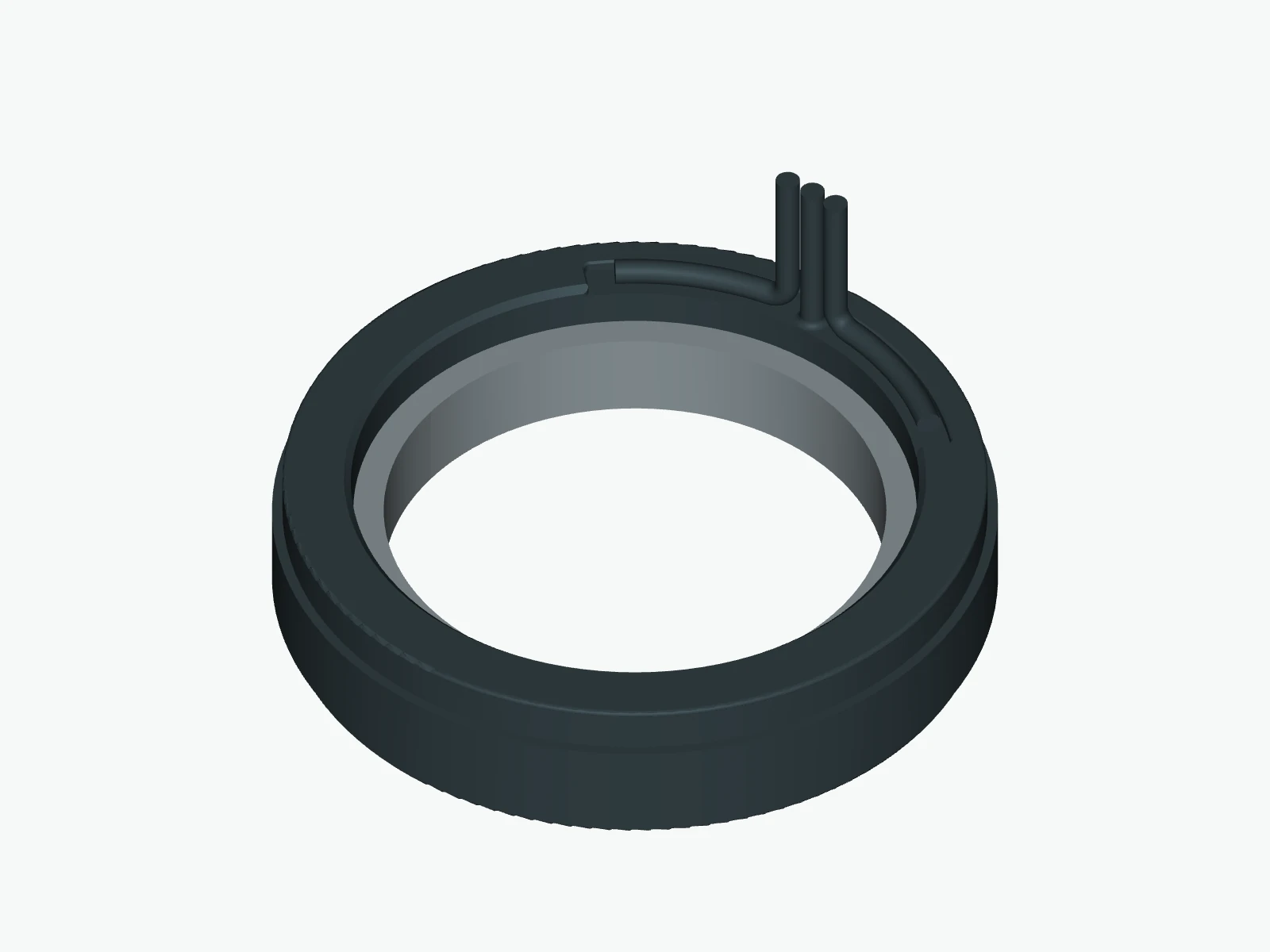
- Stator OD
- 104mm
- Rotor bore
- 72mm
- Iron stacks
- 13 / 20 / 26mm
- Winding references
- 8models
Screen your envelope across frames and compare up to four windings ↗
01 / Compare on an explicit basis
Check axial space before comparing torque.
Body limits exclude actual lead routing. The two continuous columns retain temperature-rise conditions and RMS current; neither establishes a loaded torque-speed point in your housing.
Scroll the table on narrow screens. Open a SKU for all electrical entries, timed peaks, CAD scope and direct PDF/STEP downloads.
| Model / revision | Stack / body max | Bore | Voltage range | Continuous / 55°C rise | Continuous / 105°C rise | No-load speed | Documented mass |
|---|---|---|---|---|---|---|---|
| FTM-R111-W01 ↗ rev-a Engineering review pending | 13 / ≤23 mm Drawing reference · body length disputed | 72 mm | 12–80 V | 2.20 N·m / 2.85 A RMS | 3.70 N·m / 4.73 A RMS | 726 rpm | 341 g |
| FTM-R111-W02 ↗ rev-a Engineering review pending | 13 / ≤23 mm Drawing reference · body length disputed | 72 mm | 12–80 V | 2.20 N·m / 5.72 A RMS | 3.70 N·m / 9.46 A RMS | 1430 rpm | 341 g |
| FTM-R111-W03 ↗ rev-a Engineering review pending | 13 / ≤23 mm Drawing reference · body length disputed | 72 mm | 12–80 V | 2.20 N·m / 11.44 A RMS | 3.70 N·m / 19.03 A RMS | 2860 rpm | 341 g |
| FTM-R112-W01 ↗ rev-a Engineering review pending | 20 / ≤30 mm Drawing reference · body length disputed | 72 mm | 12–80 V | 3.40 N·m / 2.85 A RMS | 5.60 N·m / 4.73 A RMS | 473 rpm | 601 g |
| FTM-R112-W02 ↗ rev-a Engineering review pending | 20 / ≤30 mm Drawing reference · body length disputed | 72 mm | 12–80 V | 3.40 N·m / 5.72 A RMS | 5.60 N·m / 9.46 A RMS | 946 rpm | 601 g |
| FTM-R112-W03 ↗ rev-a Engineering review pending | 20 / ≤30 mm Drawing reference · body length disputed | 72 mm | 12–80 V | 3.40 N·m / 11.44 A RMS | 5.60 N·m / 19.03 A RMS | 1870 rpm | 601 g |
| FTM-R113-W01 ↗ rev-a Engineering review pending | 26 / ≤36 mm Drawing reference · body length disputed | 72 mm | 12–80 V | 4.40 N·m / 2.85 A RMS | 7.30 N·m / 4.73 A RMS | 363 rpm | 652 g |
| FTM-R113-W02 ↗ rev-a Engineering review pending | 26 / ≤36 mm Drawing reference · body length disputed | 72 mm | 12–80 V | 4.40 N·m / 5.72 A RMS | 7.30 N·m / 9.46 A RMS | 726 rpm | 652 g |
Documented values are generally ±10%. No-load speed is not loaded speed, listed mass is not an independently weighed complete assembly, and matching temperature-rise labels do not establish identical cooling. No compatibility score or drop-in approval is inferred.
02 / Inspect the actual axial configurations
Each mechanical reference has its own CAD.
Use the correct geometry and revision. Shared winding images describe the reviewed mechanical reference, not internal coil construction or identical mass.
13 mm stack · ≤23 mm drawing body · about 46.25 mm full CAD axial envelope with modeled leads.
FTM-R111-W01 / FTM-R111-W02 / FTM-R111-W03: Axial dimensions are documentation references for configuration discussion. The final body envelope, tolerances and lead exit must be specified on the configuration drawing; these references do not establish installation fit.
Inspect this model’s dimensions & STEP ↗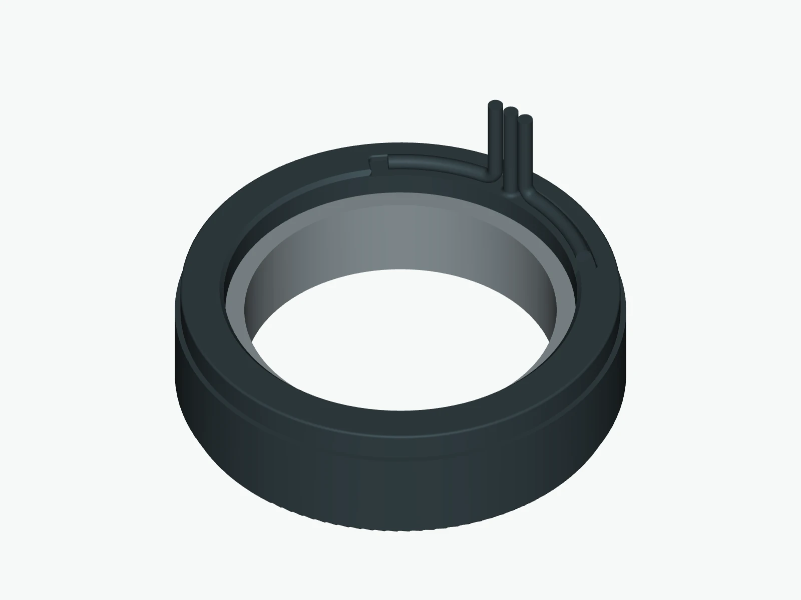
20 mm stack · ≤30 mm drawing body · about 53.25 mm full CAD axial envelope with modeled leads.
FTM-R112-W01 / FTM-R112-W02 / FTM-R112-W03: Axial dimensions are documentation references for configuration discussion. The final body envelope, tolerances and lead exit must be specified on the configuration drawing; these references do not establish installation fit.
Inspect this model’s dimensions & STEP ↗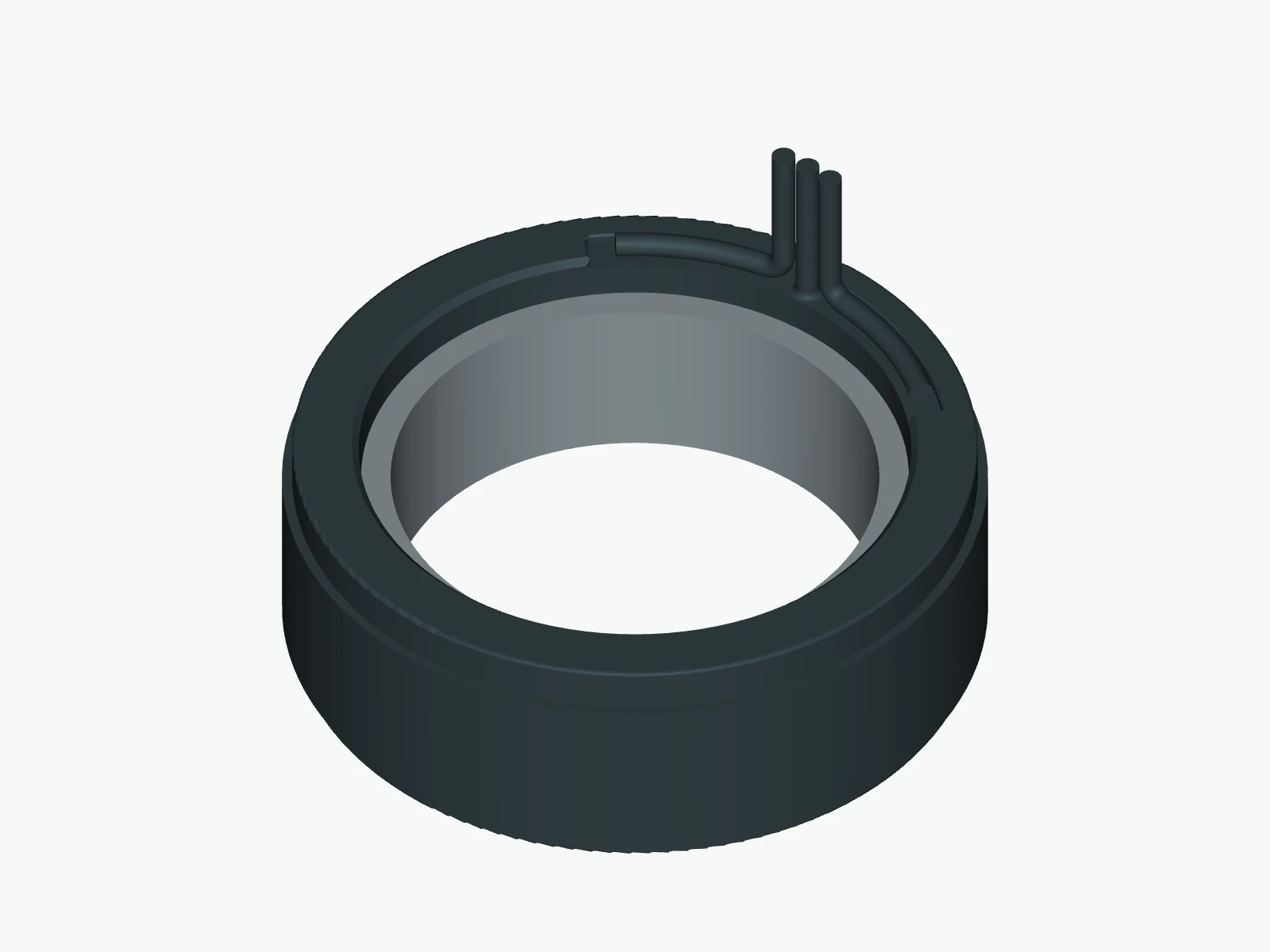
26 mm stack · ≤36 mm drawing body · about 59.25 mm full CAD axial envelope with modeled leads.
FTM-R113-W01 / FTM-R113-W02: Axial dimensions are documentation references for configuration discussion. The final body envelope, tolerances and lead exit must be specified on the configuration drawing; these references do not establish installation fit.
Inspect this model’s dimensions & STEP ↗03 / Turn a candidate into an engineering brief
Fit, loaded point, duty and heat path.
Constrain the complete assembly
State maximum OD, minimum usable bore after the shaft/retention, motor body and complete wiring space. The iron stack cannot substitute for total length. Include fits and feedback hardware.
Review the winding with the drive
Provide loaded torque and speed, bus voltage and current convention. Compare resistance, inductance, constants and continuous/peak drive limits from each individual datasheet; no-load speed is only one reference entry.
Keep continuous and timed peak separate
Select an acceptable winding rise, ambient and housing heat path. Attach peak duration and recovery to torque. The documentation does not fully define repeated peak cycles or guarantee the same cooling across configurations.
Available-for-review customization includes winding/voltage matching, bore and interfaces, lead exit/length/connectors and temperature-sensor needs. Changes require a reviewed configuration, sample plan and confirmation drawing. MOQ, lead time and price are quoted against that configuration.
Before choosing a 104 mm frame.
Which engineering review remains open for FTM-R111-W01 / FTM-R111-W02 / FTM-R111-W03?
Axial dimensions are documentation references for configuration discussion. The final body envelope, tolerances and lead exit must be specified on the configuration drawing; these references do not establish installation fit. These reference values do not resolve open documentation questions or approve a fit or drive setting. Confirm the applicable configuration and documentation before selection.
Which engineering review remains open for FTM-R112-W01 / FTM-R112-W02 / FTM-R112-W03?
Axial dimensions are documentation references for configuration discussion. The final body envelope, tolerances and lead exit must be specified on the configuration drawing; these references do not establish installation fit. These reference values do not resolve open documentation questions or approve a fit or drive setting. Confirm the applicable configuration and documentation before selection.
Which engineering review remains open for FTM-R113-W01 / FTM-R113-W02?
Axial dimensions are documentation references for configuration discussion. The final body envelope, tolerances and lead exit must be specified on the configuration drawing; these references do not establish installation fit. These reference values do not resolve open documentation questions or approve a fit or drive setting. Confirm the applicable configuration and documentation before selection.
What does 104 mm describe?
It is the stator outside-diameter reference, not the complete installed assembly. The body, customer housing, shaft retention, feedback and wiring need separate space and tolerance review.
Does the same outside diameter and bore mean the motors are interchangeable?
No. Compare iron stack, rotor length, full body and lead projection, fits and retention. Shared radial dimensions do not establish axial fit, drive settings or an approved replacement.
How should I choose between winding options?
Start with a loaded torque-speed point and the drive’s continuous/peak current definitions, then review bus voltage, duty cycle and heat path. A higher speed coefficient or no-load speed alone does not select the best winding.
Why are there two continuous torque conditions?
The entries use different winding temperature rises relative to ambient. They are not absolute winding-temperature limits. Identical labels do not prove identical cooling or test conditions; confirm the application heat path.
Can I use the largest peak torque for repeated motion?
Keep the specified two- or ten-second duration and current with the torque. Recovery time, ambient, housing cooling and winding limits are not fully established by those entries. Send the complete repeat cycle for review.
Where are the STEP files and customization details?
Open the exact model page for its applicable mechanical STEP, winding datasheet, revision and file checksums. Winding, interfaces and leads can be reviewed against your brief; the order configuration and commercial terms require confirmation.
04 / Request the configuration you need
Send the loaded duty and complete envelope.
A frame-size request alone is insufficient to confirm a winding. Include your heat path, drive definitions, peak/recovery cycle, shaft/feedback needs and quantities.
Turn selection requirements into an engineering review
A dimensional shortlist still needs winding, thermal and installation evidence for the actual assembly.
Look up a model, screen the envelope and compare winding referencesUse the record’s revision and open reviews; a shortlist is not engineering confirmation.