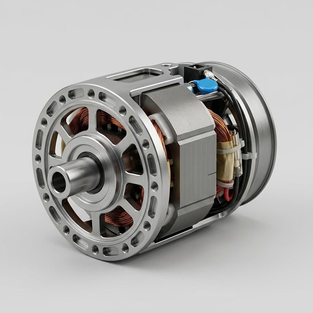
Frameless Torque Motor Cooling Guide for Continuous Duty
Compare frameless torque motor thermal management options, validation tests, and RFQ questions before contacting suppliers or our engineering team.
Peak torque tells you what a frameless torque motor can do for a few seconds. Continuous torque tells you what your cooling path can handle forever.
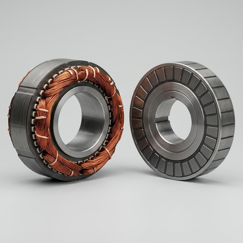
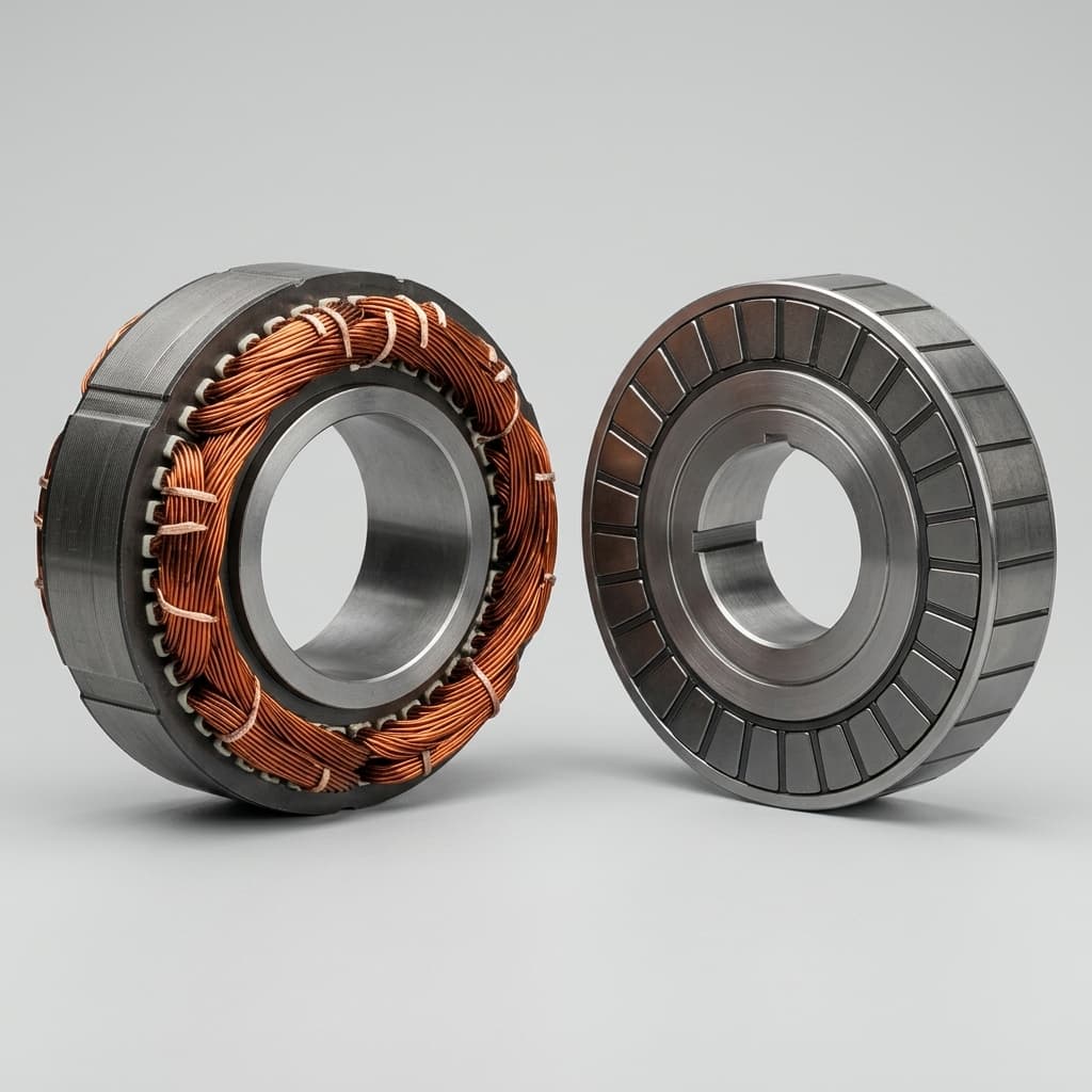
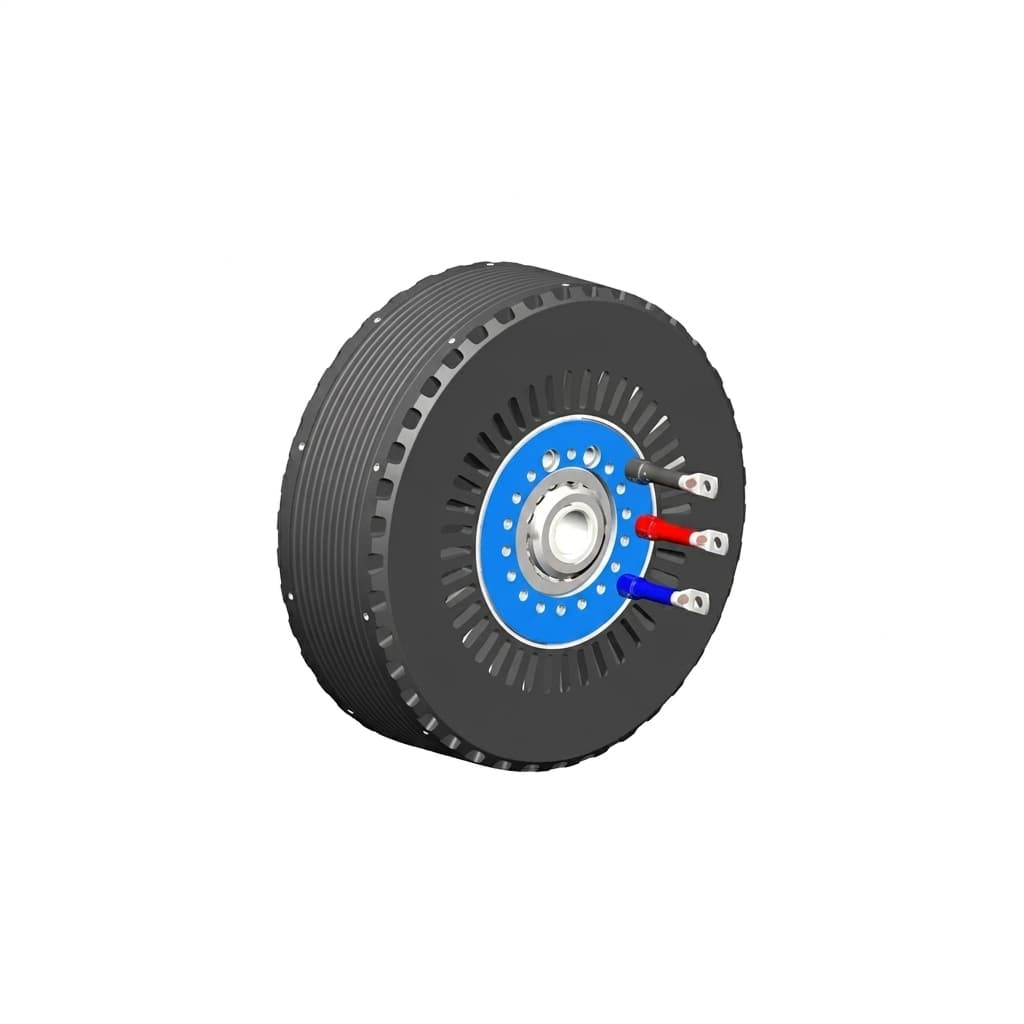
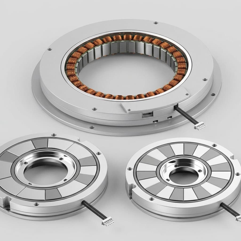
For engineers and buyers, thermal management is the hardest part of integrating a frameless torque motor. Because these motors ship without a frame or external heatsink, the OEM’s machine structure becomes the primary thermal path. If the housing cannot pull heat away from the stator effectively, the motor will derate—often significantly below the catalog specification.
This guide breaks down how to evaluate thermal boundaries, compare cooling strategies, mitigate failure risks, and ensure your procurement specifications match reality. We will explore the nuances of thermal interfaces, liquid versus air cooling, and the precise questions you must ask your suppliers to avoid costly overheating issues in the field.
When evaluating a frameless motor datasheet, the "Continuous Torque" (Tc) is not an absolute property of the electromagnetic design alone. It is the torque the motor can produce continuously while mounted to a specific, theoretical heatsink (often an aluminum plate of a given dimension in 25°C ambient air) without exceeding its maximum winding temperature (usually 155°C or 180°C).
If you mount that same stator in a sealed robotic joint made of thin-walled titanium or a carbon-fiber enclosure, the thermal resistance increases dramatically. The heat cannot escape, the windings get hot much faster, and the actual continuous torque you can draw drops. This mismatch between lab conditions and field conditions is the number one cause of frameless motor underperformance and field failures.
Every 10°C rise in operating temperature above the rated limit effectively halves the lifespan of the motor's insulation. Poor thermal management doesn't just mean less torque; it means premature failure in the field. When windings run hot continually, the resin binding the copper degrades, eventually leading to a short circuit. Furthermore, high stator temperatures can radiate across the air gap, heating the rotor and posing severe risks to the permanent magnets.
Understanding the application boundaries of your frameless motor is crucial for proper thermal management. Frameless motors are not a one-size-fits-all solution. They excel in high-precision, low-weight, and compact footprint scenarios like collaborative robots (cobots), aerospace gimbals, and medical imaging devices.
However, they have strict limitations that buyers and engineers must respect:
Environment: If the ambient temperature regularly exceeds 40°C, the thermal gradient (ΔT) between the stator and the environment shrinks, drastically reducing continuous torque capacity.
Enclosure: Completely sealed IP67/IP69K enclosures trap heat. Without active liquid cooling or a massive heat sink, a frameless motor inside a sealed enclosure will only be able to operate at a fraction of its rated continuous torque.
Duty Cycle: Applications with a low RMS torque but high peak torque (like indexing tables) can often rely on natural conduction. Conversely, applications with high sustained RMS torque (like centrifuges or extruders) necessitate active liquid cooling.
For compact joints, the thermal path must be reviewed together with reducer, bearing, encoder, and cable routing constraints. Use the robot joint motor selection checklist if the motor sits inside a cobot or humanoid actuator.
There are four primary ways to cool a frameless torque motor. The right choice depends on the duty cycle, available space, system complexity, and budget.
Pros: Low to moderate cost, noticeable boost in continuous torque and heat dissipation.
Cons: Introduces acoustic noise, requires venting which lowers the IP rating (susceptible to water and dust ingress), and makes the motor vulnerable to debris accumulation on the windings.
A highly effective method where water or a water/glycol mixture is circulated through cooling channels machined into the stator housing or an intermediate cooling sleeve.
Mechanism: The high specific heat capacity of liquid removes massive amounts of thermal energy quickly, pulling heat away from the stator outer diameter.
Pros: High torque density, allows for very compact motor designs, isolates heat from the rest of the sensitive machine components.
Cons: High complexity. Requires external pumps, chillers, rotary seals, and plumbing. Risk of leaks which can catastrophically damage the motor and associated electronics.
The most extreme cooling method, involving dielectric oil sprayed directly onto the windings or circulated through the stator slots.
Mechanism: Direct contact with the heat source eliminates the thermal resistance of the stator laminations and the housing interface entirely.
Ideal For: EV traction motors, high-speed generators, extreme-duty aerospace axes.
Pros: Absolute highest thermal dissipation and torque density achievable.
Cons: Very high cost and complexity. Requires dedicated oil management systems, filtration, and extreme sealing. Fluid drag (windage) can reduce high-speed efficiency.
To assist buyers and system architects in selecting the correct cooling architecture, refer to the following decision matrix. This evaluates the trade-offs across multiple engineering and commercial dimensions to guide your purchasing decision.
Cooling Strategy
Torque Density Multiplier
System Complexity
Maintenance Requirement
Ideal Ambient Temp
Acoustic Noise
Leakage Risk
Relative Cost
Primary Use Case
Natural Conduction
1.0x (Baseline)
Lowest
None
30°C or lower
Silent
None
Low
Medical robotics, gimbals
Enhanced Conduction (Finned)
1.2x
Low
None
40°C or lower
Silent
None
Low-medium
Industrial automation joints
Forced Air (External)
1.5x
Moderate
Low (Filter changes)
40°C or lower
Moderate
None
Low-medium
AGVs, textile machinery
Forced Air (Internal)
1.8x
Moderate
High (Dust buildup)
35°C or lower
High
None
Medium
Spindles, dry environments
Liquid Jacket (Water/Glycol)
2.5x
High
Moderate (Fluid checks)
50°C or lower
Low (Pump noise)
High
High
CNC, heavy robotics
Direct Liquid Spray (Oil)
3.5x+
Highest
High (Filtration, seals)
80°C or lower
Low
Extreme
Very high
EV traction, aerospace
Phase Change / Heat Pipes
2.0x
Very High
Low
60°C or lower
Silent
Low
Very high
Spacecraft, vacuum environments
Peltier / Thermoelectric
1.1x
High
Moderate
25°C or lower
Silent
None
Medium
Specialized optics
Note: The Torque Density Multiplier is an approximation relative to a standard natural conduction baseline. Actual values depend heavily on specific motor geometry and thermal gradients.
Even if you have a massive aluminum housing or a powerful liquid chiller, the heat must cross the boundary between the stator's outer diameter (OD) and the housing's inner diameter (ID). Microscopic air gaps act as potent thermal insulators.
Thermal Shrink Fit: Heating the housing so it expands, dropping the stator in, and letting it cool. This creates high contact pressure and excellent thermal transfer. It is the gold standard for high-performance frameless integration.
Press Fit: Mechanically forcing the stator into a slightly undersized housing. Good thermal transfer, but can deform thin-walled housings and requires precise tolerancing to avoid damaging the stator laminations.
Adhesive Bonding: Using a slip fit and filling the gap with retaining compound. Standard structural adhesives are thermal insulators. You must specify a thermally conductive epoxy or use a very tight slip fit with a thin layer of high-performance Thermal Interface Material (TIM).
When designing the thermal interface, mechanical engineers must strictly control several dimensions:
Concentricity and Runout: Ensures even thermal contact and prevents localized hot spots on one side of the stator.
Surface Roughness (Ra): A smoother surface finishes (typically Ra 0.8 or better) on the housing ID minimizes the microscopic air pockets between the stator OD and the housing.
Interference Margin: In a shrink fit, the exact delta between the stator OD and housing ID dictates the contact pressure. Too little, and thermal transfer suffers. Too much, and the stator laminations may warp or buckle.
Failing to properly manage the thermal output of a frameless torque motor leads to three catastrophic failure modes. Understanding these risks is essential for procurement and quality assurance teams.
Unlike electromagnets, the permanent magnets on the rotor (typically Neodymium Iron Boron, NdFeB) are highly sensitive to temperature. If the rotor temperature exceeds the magnet's rated coercivity threshold (often between 120°C and 150°C, depending on the grade), the magnets will permanently lose field strength. This results in an irreversible drop in the motor's torque constant (Kt). To produce the same torque, the motor will now draw more current, generating even more heat, leading to a rapid death spiral.
Mitigation: Specify high-temperature magnet grades (e.g., UH or EH grades) for demanding applications and ensure the stator ID does not radiate excessive heat across the air gap. Use rotor cooling techniques if necessary.
As mentioned via the Arrhenius rule, heat degrades the enamel coating on the copper wire and the slot liners separating the phases. When this insulation becomes brittle and cracks, it leads to phase-to-phase or phase-to-ground short circuits. This will instantly destroy the motor and potentially damage the servo drive.
Mitigation: Utilize Class H (180°C) or Class N (200°C) insulation systems and embed thermistors (PT1000/PT100) deeply within the end turns to trigger drive faults before critical temperatures are reached.
Extreme heat causes thermal expansion. If the stator and the housing have significantly different coefficients of thermal expansion (CTE)—for instance, a steel stator in a lightweight magnesium housing—the expansion can alter the interference fit. If the fit loosens, thermal transfer plummets. If the housing restricts expansion too rigidly, the stator stack may warp, causing the inner diameter to scrape against the rotor.
Mitigation: Match CTEs where possible, or perform rigorous Finite Element Analysis (FEA) to simulate thermal cycling stresses over the entire operating temperature range.
Before finalizing an order for a frameless torque motor, verify these thermal parameters with your mechanical engineering team and clearly communicate them to the motor manufacturer. Do not assume the catalog specs will magically apply to your custom machine.
Housing Material Conductivity: Is the housing aluminum (167 W/m·K), steel (45 W/m·K), or titanium (16 W/m·K)? Communicate this exact material specification to the vendor.
Ambient Temperature: What is the maximum operating ambient temperature for the final machine? Ensure the vendor knows if the machine operates in a 40°C factory rather than a 20°C lab.
Duty Cycle Calculation: Have you mapped the RMS (Root Mean Square) continuous torque requirement over the full motion profile? Provide the exact motion profile (acceleration, constant velocity, deceleration, dwell) to the supplier.
Stator Mounting Method: Are you using a thermal shrink fit, or relies on adhesive? If adhesive, explicitly ask the vendor to recommend a thermally conductive epoxy compatible with their stator lamination coating.
Thermal Modeling Check: Has the motor supplier run a thermal model (like Motor-CAD) using your housing dimensions and material properties rather than their standard test plate? Demand application-specific thermal curves.
Sensor Placement: Are temperature sensors (PT1000, thermistors, PTCs) placed directly on the hottest part of the end turns to provide accurate feedback to the servo drive?
Relying solely on software modeling is risky. Before moving to mass production, rigorous empirical testing must validate the thermal assumptions. The procurement and QA teams must insist on the following validation steps:
Locked-Rotor Thermal Profiling: Apply a constant current equivalent to the application's RMS requirement while the motor is locked (zero speed). Log the temperature rise over time until thermal equilibrium is reached. This isolates the conductive and convective cooling paths from any rotational airflow (windage) effects.
Dynamometer Continuous Load Testing: Run the motor on a dyno at the application's average speed and continuous torque. This provides a realistic picture of iron losses (eddy currents and hysteresis), which increase with speed and contribute significantly to total heating.
Thermography and Hot-Spot Identification: Use FLIR thermal imaging cameras on the exposed parts of the assembly to identify thermal bottlenecks. If the housing is cool but the windings are critical, the stator-to-housing interface is failing.
Use a controlled test sheet so procurement can compare supplier claims against the same boundary conditions:
Test input
Required record
Why it matters
Motor revision
Model, winding, stack length, rotor magnet grade
Prevents comparing different electromagnetic builds
Housing material
Alloy, wall thickness, surface finish, coating
Defines the conductive path from stator OD to ambient
Why does my frameless motor overheat before reaching the catalog continuous torque?
Catalog continuous torque ratings assume a specific aluminum or steel heatsink surface area. If your actual housing is smaller, uses a material with lower thermal conductivity (like stainless steel or titanium), or lacks ambient airflow, the motor cannot dissipate heat fast enough and will overheat at the rated continuous current.
Is liquid cooling necessary for all frameless torque motors?
No. For many low-duty cycle or low-speed positioning applications, natural convection or structural conduction is completely sufficient. Liquid cooling is typically required only when maximizing torque density in continuous high-speed or high-load operations, such as CNC spindles, large centrifuges, or heavy extrusion lines.
How does the mounting method affect thermal performance?
Thermal transfer relies on intimate surface contact. A tight interference fit (press fit or thermal shrink fit) provides the best heat transfer from the stator to the housing. Gap-filling structural adhesives or loose sliding fits with air gaps create severe thermal resistance, drastically reducing continuous torque capacity.
What is the maximum safe temperature for a frameless motor?
Most frameless motors use Class F (155°C) or Class H (180°C) winding insulation. However, the permanent magnets on the rotor (often NdFeB) usually have lower limits, around 120°C to 150°C, above which they can permanently demagnetize. It is crucial to monitor both winding and rotor temperatures in extreme applications.
Can I use thermal paste between the stator and my housing?
Yes, thermal interface materials (TIMs) or thermally conductive epoxies are often used to eliminate microscopic air gaps between the stator and housing when a slip-fit is utilized. This significantly improves heat transfer compared to dry metal-on-metal contact with loose tolerances.
What should I ask my supplier if I am experiencing thermal issues in my prototype?
First, ask them to review your mounting CAD and housing material. Provide them with the actual PT1000 temperature data logged during your motion profile. Request an application-specific thermal derating curve based on your actual housing geometry, rather than the catalog heatsink.
How can I test the thermal limits of my assembly before mass production?
Conduct a locked-rotor thermal test or a continuous dynamometer run using your actual production housing. Instrument the housing and the ambient air with thermocouples, and log the internal winding thermistor data until temperatures stabilize to empirically determine your true continuous thermal limit.
When buying frameless torque motors, you are purchasing raw electromagnetic potential. Unlocking that potential safely requires deliberate thermal engineering. By standardizing your cooling strategy early, understanding the severe impact of the stator-to-housing interface, and ensuring tight mechanical integration, you can achieve the continuous torque density required for high-performance direct-drive axes.
Why does my frameless motor overheat before reaching the catalog continuous torque?
Catalog continuous torque ratings assume a specific aluminum or steel heatsink surface area. If your actual housing is smaller, uses a material with lower thermal conductivity, or lacks airflow, the motor cannot dissipate heat fast enough and will overheat at the rated continuous current.
Is liquid cooling necessary for all frameless torque motors?
No. For many low-duty cycle or low-speed positioning applications, natural convection or structural conduction is sufficient. Liquid cooling is typically required when maximizing torque density in continuous high-speed or high-load operations.
How does the mounting method affect thermal performance?
Thermal transfer relies on surface contact. A tight interference fit (press fit or thermal shrink fit) provides the best heat transfer from the stator to the housing. Gap-filling adhesives or loose sliding fits with air gaps create thermal resistance, reducing continuous torque capacity.
What is the maximum safe temperature for a frameless motor?
Most frameless motors use Class F (155°C) or Class H (180°C) winding insulation. Permanent magnets (often NdFeB) usually have lower limits, around 120°C to 150°C, above which they can permanently demagnetize. It is crucial to monitor both winding and rotor temperatures.
Can I use thermal paste between the stator and my housing?
Yes, thermal interface materials (TIMs) or thermally conductive epoxies are often used to eliminate microscopic air gaps between the stator and housing, significantly improving heat transfer compared to dry metal-on-metal contact.
Author
Jimmy Su
Frameless torque motor sourcing and application engineering. 10+ years in industrial motion control supply chain between China and global OEM markets.