Frameless Torque Motor Sizing Mistakes: A Guide for Procurement and Engineering Teams
Avoid frameless torque motor sizing mistakes: align RMS torque, thermal path, winding, and drive limits before RFQ. Send real duty-cycle data for review.
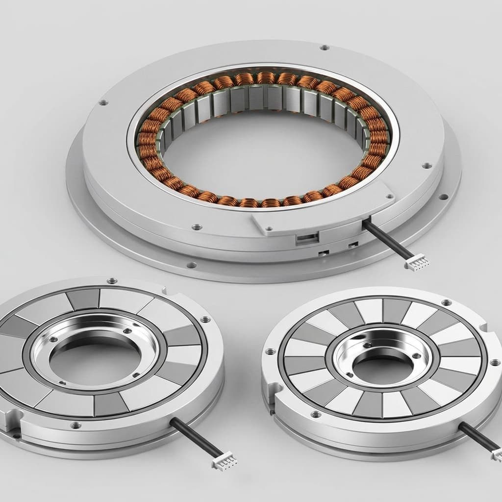
Frameless torque motors offer unmatched precision, high torque density, and compact form factors for robotics, medical devices, and aerospace systems. By eliminating the shaft, bearings, and outer housing, these direct-drive components allow engineers to integrate the electromagnetic core directly into the machine's mechanical structure.
However, this tight integration blurs the lines between electrical design, mechanical engineering, and procurement. When purchasing standard housed servo motors, sizing is often treated as a straightforward exercise. But with frameless torque motors, selecting the wrong size doesn't just mean swapping a part—it often requires redesigning the machine's structural castings, altering thermal management strategies, and upgrading expensive servo drives.
For procurement teams and engineering managers, the cost of a sizing mistake can easily run into thousands of dollars per machine in wasted material, oversized drives, and delayed time-to-market.
This comprehensive guide breaks down the most expensive sizing errors made when specifying frameless torque motors, how to correct them, and how procurement and engineering teams can align to source the optimal direct-drive solution.
Applicability note, published July 19, 2026: This guide is written for global OEM procurement teams, engineering managers, and motion-control engineers selecting frameless torque motors for robotics, medical equipment, aerospace mechanisms, rotary stages, and factory automation axes. It is a sizing and RFQ framework, not a substitute for supplier torque-speed curves, thermal testing in your final housing, or safety review for regulated systems.
In many traditional engineering cultures, applying a "safety factor" of 20% or 30% to motor sizing is considered a standard best practice. In the world of direct-drive frameless motors, this mindset is a costly error.
Because frameless motors are embedded into the joint or axis of the machine, an oversized motor demands a larger mechanical envelope. A motor with a larger outside diameter (OD) or longer stack length requires a larger, heavier housing. This increased mass at the joint requires stronger bearings. If the joint is part of a robotic arm, the increased mass of the joint itself now becomes a parasitic load that the next motor down the kinematic chain must move, creating a compounding cycle of oversizing.
Furthermore, a larger motor requires more current to reach its operating speeds and overcome its own higher inertia. This forces procurement to buy higher-amp servo drives, thicker cables, and larger power supplies. What started as a "safe" 20% torque margin can easily inflate the Bill of Materials (BOM) cost of an axis by 50%.
To avoid this, engineering and procurement teams must clearly understand the difference between the loads the motor must hold continuously versus the loads it must handle for a fraction of a second.
The most frequent and expensive mistake in frameless motor sizing is confusing peak torque requirements with continuous torque requirements.
Every frameless motor datasheet provides two critical torque values:
Continuous Torque (Tc): The maximum torque the motor can produce indefinitely without exceeding its maximum winding temperature (often 130°C or 155°C), assuming a specific cooling path.
Peak Torque (Tp): The maximum torque the motor can produce for a very short duration (typically a few seconds) before the windings overheat and sustain damage.
Many applications—such as robotic arms or index tables—spend most of their time moving at constant velocity or holding a position, which requires relatively low torque. They only require maximum torque during rapid acceleration, sudden deceleration, or when recovering from an emergency stop.
If an engineer calculates that a joint needs 100 Nm of torque to accelerate a payload in 100 milliseconds, and then passes a requirement to procurement for a "100 Nm continuous motor," the result will be disastrous. A motor capable of 100 Nm continuously might be three times larger and heavier than a motor capable of 100 Nm peak and 30 Nm continuously.
The Solution: Always define the motion profile. Divide the machine's requirements into dynamic (acceleration/deceleration) loads and static (friction, gravity, constant speed) loads. Ensure the motor's Peak Torque exceeds the dynamic maximums, and the Continuous Torque exceeds the steady-state requirements.
Visualizing Duty Cycle Limits
Notice how the actual load only enters the peak region for short bursts, while the steady state stays below the continuous limit.
Closely related to the peak vs. continuous mistake is the failure to calculate Root Mean Square (RMS) torque.
A duty cycle represents the ratio of time a motor spends working versus resting. In highly dynamic applications, torque fluctuates wildly. The motor might push hard for 2 seconds, coast for 5 seconds, hold position for 3 seconds, and then rest for 10 seconds.
Because heat generation inside a motor is proportional to the square of the current (I²R losses), you cannot simply take an average of the torque values. You must calculate the RMS torque for the entire cycle. If the calculated RMS torque exceeds the motor's rated Continuous Torque, the motor will eventually overheat and fail, even if no single event exceeds the Peak Torque limit.
Procurement teams should be wary of any RFQ that requests a specific motor size without providing a duty cycle or an RMS calculation. Buying a motor without knowing its intended thermal workload is a recipe for premature field failures and expensive warranty claims.
When engineers realize a selected motor does not have enough torque, the instinct is often to look for a "longer" version of the same motor. Motor manufacturers frequently offer families of motors with the same outer diameter but varying stack lengths (e.g., 25mm, 50mm, 75mm lengths).
While increasing the stack length does increase torque linearly, it is not always the most efficient choice for space, weight, or cost.
In electromagnetic design, torque scales linearly with motor length, but it scales with the square of the air gap diameter. This means that a relatively small increase in the motor's diameter will yield a massive increase in torque capability compared to increasing its length.
For example, if you are space-constrained axially (along the shaft), you might be tempted to force a long, skinny motor into a design. But if you have room to grow radially, stepping up to the next larger diameter frame size will provide significantly more torque for a given volume and weight.
For buyers, if an engineer is requesting a highly customized, ultra-long stack length of a small diameter motor, it is worth questioning whether the mechanical envelope can be relaxed radially to use a cheaper, standard-length, larger-diameter motor.
If the radial and axial envelope cannot move, review custom OEM motor assemblies before asking suppliers to quote a nonstandard stack length. A custom path can be correct, but it should be chosen because the axis requires it, not because the first sizing pass skipped a standard diameter option.
When you buy a standard housed servo motor, the manufacturer provides torque ratings based on the heat dissipation of the factory housing.
When you buy a frameless torque motor, you are only buying the electromagnetic core. You are entirely responsible for the housing. This means the datasheet's Continuous Torque rating is highly conditional.
Most frameless motor datasheets state the assumptions used to generate their continuous torque ratings. Common assumptions include:
The stator is mounted in a 250mm x 250mm x 12mm unpainted aluminum heat sink.
The ambient air temperature is 25°C.
There is natural convection (no fans).
If your machine is made of stainless steel (which is a poor conductor of heat compared to aluminum), or plastic, or if the motor is enclosed in a sealed, unventilated robotic joint operating in a 40°C factory, the motor will not be able to dissipate heat effectively. In these real-world conditions, a motor rated for 10 Nm continuously might only be capable of 5 Nm continuously before the windings reach their thermal limit.
The Procurement Check: Before finalizing a PO, procurement must ask engineering: "Does our mechanical housing provide the thermal dissipation required to meet the datasheet torque? Have we derated the motor for our actual ambient conditions?"
A motor's mechanical dimensions are only half the equation. The electrical winding—how the copper wire is coiled inside the stator—determines the motor's torque constant (Kt) and voltage constant (Ke).
A common error is selecting a motor based on its torque capability but choosing a winding that requires more current than the chosen servo drive can supply, or a winding that generates too much back-EMF for the available DC bus voltage.
Voltage Limit (Back-EMF): As a motor spins faster, it acts like a generator, creating voltage that pushes back against the servo drive. If the motor's voltage constant (Ke) is too high, and the target speed is very fast, the back-EMF may exceed the drive's DC bus voltage. When this happens, the motor simply cannot spin any faster, regardless of how much torque it has.
Current Limit: If you choose a winding with a very low torque constant (Kt), the motor will require massive amounts of current to generate the required torque. If this current exceeds the continuous or peak current rating of your servo drive, you will have to buy a significantly larger, more expensive drive.
The motor winding, DC bus voltage, and servo drive current limit must be solved as a single coupled equation. Changing any one of these variables late in the procurement cycle will break the system.
Before sending an RFQ to a frameless torque motor manufacturer, engineering and procurement teams should review this checklist together. Sending a complete data package dramatically reduces quote turnaround time and prevents costly late-stage revisions.
Motion Profile Defined: We have mapped out the specific acceleration, constant velocity, and dwell times (duty cycle) rather than just a single torque number.
RMS Torque Calculated: We have calculated the thermal equivalent continuous torque (RMS) required for the most aggressive operating cycle.
Peak Torque Identified: We know the absolute maximum torque required for emergency stops or peak acceleration.
Thermal Path Confirmed: We have identified the material of the housing (aluminum, steel, etc.) and know the maximum ambient temperature the machine will operate in.
Envelope Flexibility Checked: We know which dimensions are strictly fixed (e.g., maximum OD, minimum bore ID) and which have some flexibility to accommodate standard motor sizes.
Electrical Constraints Locked: We have defined the available DC bus voltage and the maximum continuous/peak current our selected servo drive can provide.
Environmental Needs Noted: We have defined any harsh environmental requirements (vacuum, high radiation, chemical washdown) that would affect material selection.
Q: Can we just use the sizing software provided by our servo drive manufacturer?
A: Drive sizing software is excellent for calculating load inertias and RMS torque profiles. However, it often assumes housed motors with known thermal characteristics. When using drive software, you must manually cross-reference the required RMS torque against the frameless motor's derated thermal capabilities in your specific housing.
Q: What is "cogging torque" and does it affect sizing?
A: Cogging torque is the magnetic "bumpiness" felt when rotating a permanent magnet motor without power. While it doesn't drastically change the gross torque sizing, high cogging torque can cause velocity ripple at low speeds. If your application requires ultra-smooth scanning or pointing, you must specify low-cogging motor designs, which sometimes have slightly lower overall torque density than high-cogging alternatives.
Q: How much margin should we add to our torque calculations?
A: Because direct drive systems eliminate gearboxes, there are no gearbox inefficiencies or compliance to worry about. If your load calculations, friction estimates, and thermal models are highly accurate, a margin of 10% to 15% on RMS torque is usually sufficient. Arbitrary 50% margins will destroy the size and weight benefits of choosing a frameless motor.
Q: Is it cheaper to use a smaller motor with forced air cooling?
A: Often, yes. If space is severely restricted, adding forced air or liquid cooling channels to the machine housing can significantly increase the continuous torque capability of a small frameless motor. However, this adds complexity and potential points of failure to the machine.
Specifying a frameless torque motor is a multidisciplinary engineering challenge. Because the motor relies on the customer's mechanics and electrical architecture to function, sizing mistakes reverberate through the entire BOM, driving up costs and causing severe project delays.
By shifting the focus from "peak torque capability" to RMS torque, thermal dissipation paths, and matched electrical windings, procurement teams can protect their budgets and ensure engineers get exactly the performance they need.
Ready to select the right motor for your next axis?
Avoid the guesswork. Contact our engineering team with your motion profile, spatial envelope, and electrical limits. We will help you navigate the tradeoffs between standard product families and custom OEM assemblies to find the most cost-effective, high-performance direct drive solution.
Why is it a mistake to size a frameless motor based purely on peak torque?
Peak torque is only needed for short bursts of acceleration or emergency stops. Sizing a motor so its continuous rating matches your peak requirement leads to a massively oversized, overweight, and expensive motor.
How does the motor's diameter affect torque density compared to its length?
Torque scales linearly with the stack length of the motor, but it scales with the square of the air gap diameter. Increasing the OD slightly is often a much more efficient way to gain torque than making the motor significantly longer.
What is RMS torque and why does it matter for procurement?
Root Mean Square (RMS) torque represents the continuous thermal equivalent of your varying load cycle. Procurement needs the engineering team to calculate RMS torque to ensure the selected motor will not overheat during continuous operation, preventing costly field failures.
Can the customer housing change a frameless motor's continuous torque rating?
Yes. Frameless motors rely on the customer's mechanical structure for heat dissipation. If the motor is placed in an unventilated plastic housing, its actual continuous torque will be far lower than the datasheet value, which often assumes an aluminum heat sink.
Author
Jimmy Su
Frameless torque motor sourcing and application engineering. 10+ years in industrial motion control supply chain between China and global OEM markets.