Custom configuration reference · Final axial envelope to be agreed on your configuration drawing.
Frameless motor reference / 60 mm frame
FTM-R106-W0160 mm frameless torque motor
FTM-R106-W01 is a 60 mm frameless motor reference with a 35 mm rotor bore and 26 mm iron stack. Its 25 rpm/V winding documents 0.93 N·m at 2.04 A RMS under the 55°C winding-rise condition. Use the references to discuss your winding, housing and duty cycle.
rev-a · Documentation reviewed 2026-10-31 · Standard configuration subject to order confirmation
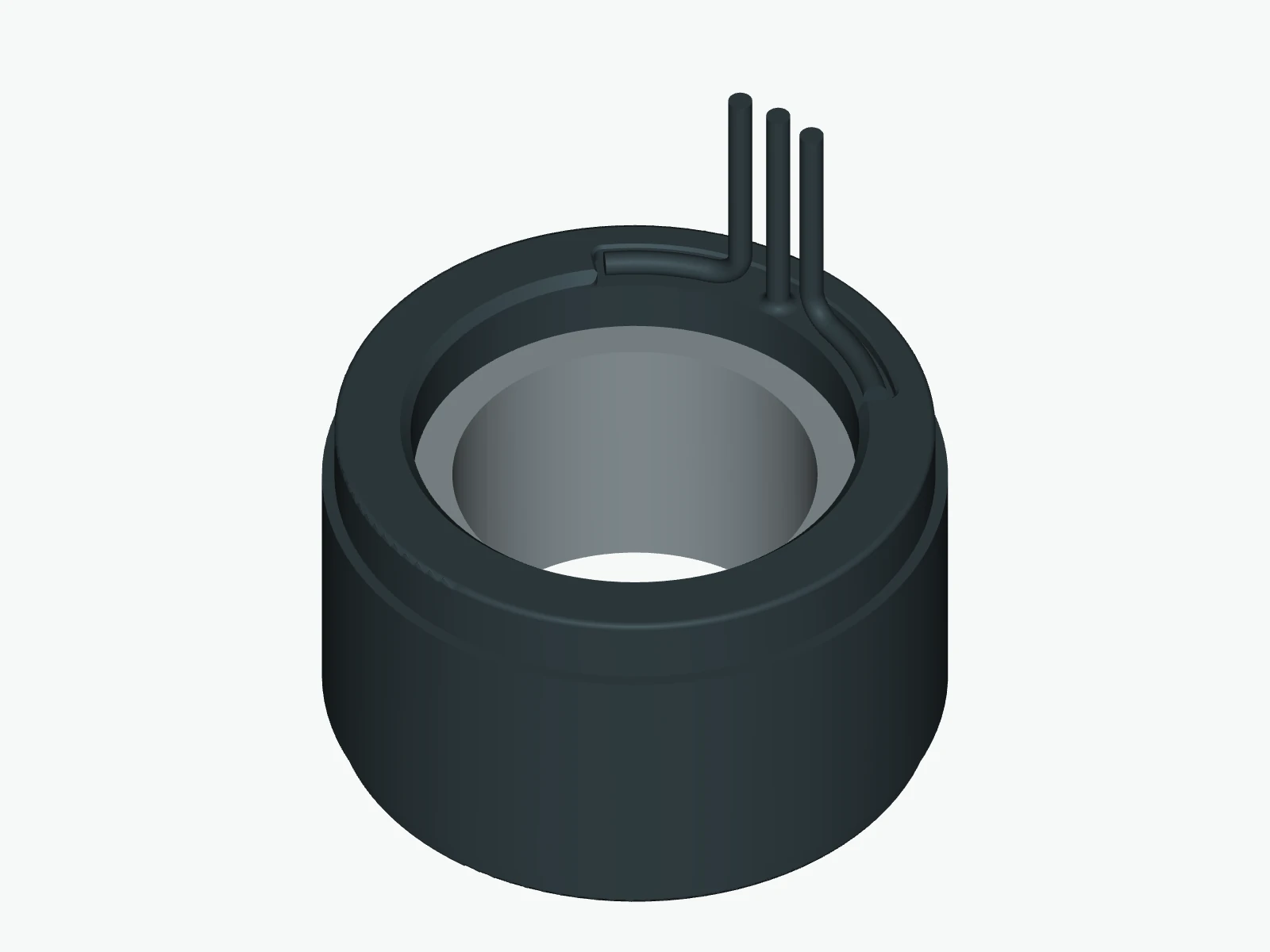
- Stator OD
- 60mm
- Rotor bore
- 35mm
- Iron stack
- 26mm
- Final axial envelope
- To agreeon drawing
01 / Choose the operating basis
Keep temperature rise and peak duration with the torque.
The same winding has different documented ratings under different limits. Start with your duty cycle and housing heat path.
Continuous torque by winding temperature rise
| Rise | Torque | RMS current |
|---|---|---|
| 55°C | 0.93 N·m | 2.04 A |
| 105°C | 1.55 N·m | 3.41 A |
Peak torque by duration
| Duration | Torque | RMS peak current |
|---|---|---|
| 10 s | 4 N·m | 9.13 A |
| 2 s | 6.5 N·m | 18.26 A |
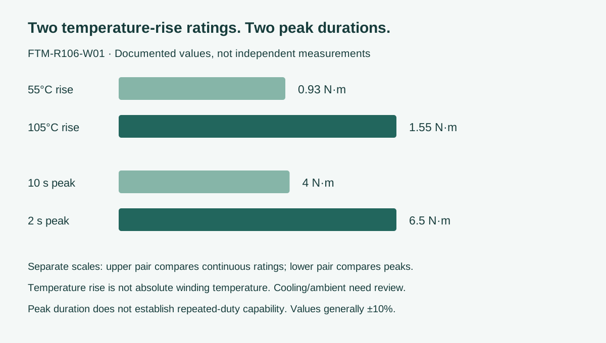
Documented performance and electrical entries are generally ±10%. Temperature rise is relative to ambient, not the absolute winding temperature. The source documentation does not fully define the housing heat sink, ambient temperature or repeated-peak recovery cycle. These ratings require application review; they are not independently measured results. Reference publication does not establish a configured production rating.
Axial dimensions are documentation references for configuration discussion. The final body envelope, tolerances and lead exit must be specified on the configuration drawing; these references do not establish installation fit.
25 rpm/V: review this winding against the drive
FTM-R106-W01 uses the documented 25 rpm/V speed-coefficient reference. 1210 rpm is the documented no-load reference. The separate 930 rpm loaded-speed entry has no complete approved torque/drive/thermal point. Neither entry supplies a continuous torque-speed curve or a speed guarantee at the listed torque. Current conventions and the actual loaded point must be reviewed with the drive.
0.93 and 1.55 N·m use different temperature rises
FTM-R106-W01 documents 0.93 N·m at 2.04 A RMS for 55°C winding rise, and 1.55 N·m at 3.41 A RMS for 105°C rise. These are temperature rises above ambient, not absolute winding limits or guaranteed output in your housing.
26 mm stack: agree the axial envelope before housing design
26 mm is the iron stack. The 36 mm body entry is a drawing reference, not an agreed installation limit. Budget the final body, leads, shaft retention and feedback before freezing the housing. The 35 mm bare rotor bore is not the free passage after customer components are installed.
02 / Check the complete envelope
A 26 mm stack. Agree the final axial envelope. Separate space for leads.
Use the bore, body and lead-routing envelope together. Check the order drawing before fixing fits, retention or assembly tolerances.
| Parameter | Documented value / definition |
|---|---|
| Stator outside diameter | 60 mm0 / -0.07 mm |
| Stator inside diameter | 43 mm0 / -0.06 mm |
| Rotor outside diameter | 42.4 mm±0.05 mm |
| Rotor bore | 35 mm+0.03 / 0 mm |
| Iron stack length | 26 mm±0.20 mm |
| Rotor axial length | 26 mm±0.05 mm |
| Motor body axial envelope | ≤36 mmDrawing reference only; final configured envelope and tolerances must be specified before installation. |
| Power lead length | 200 mmDrawing reference; customization available for review |
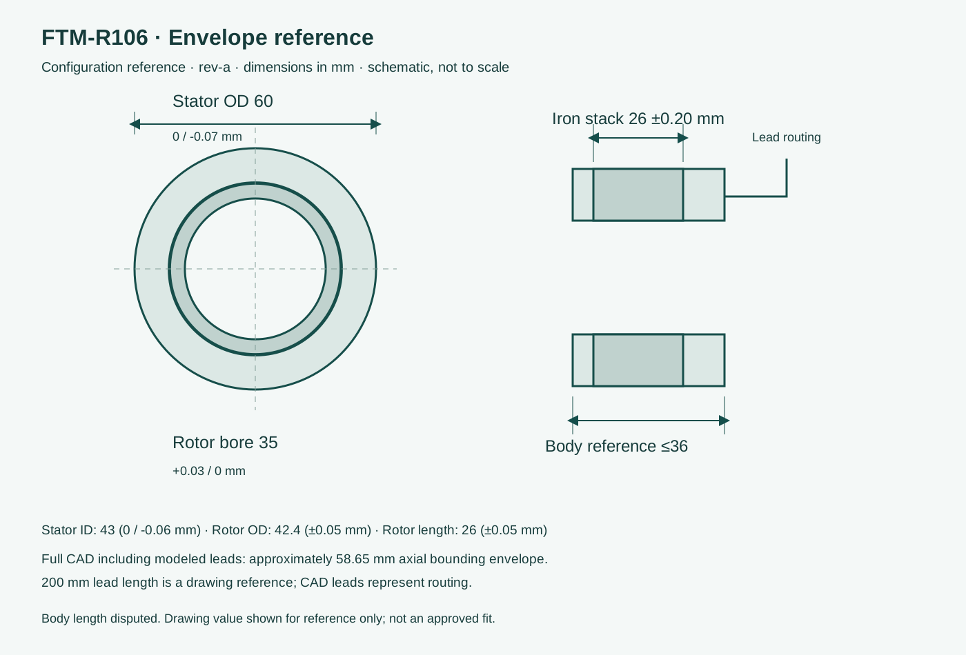
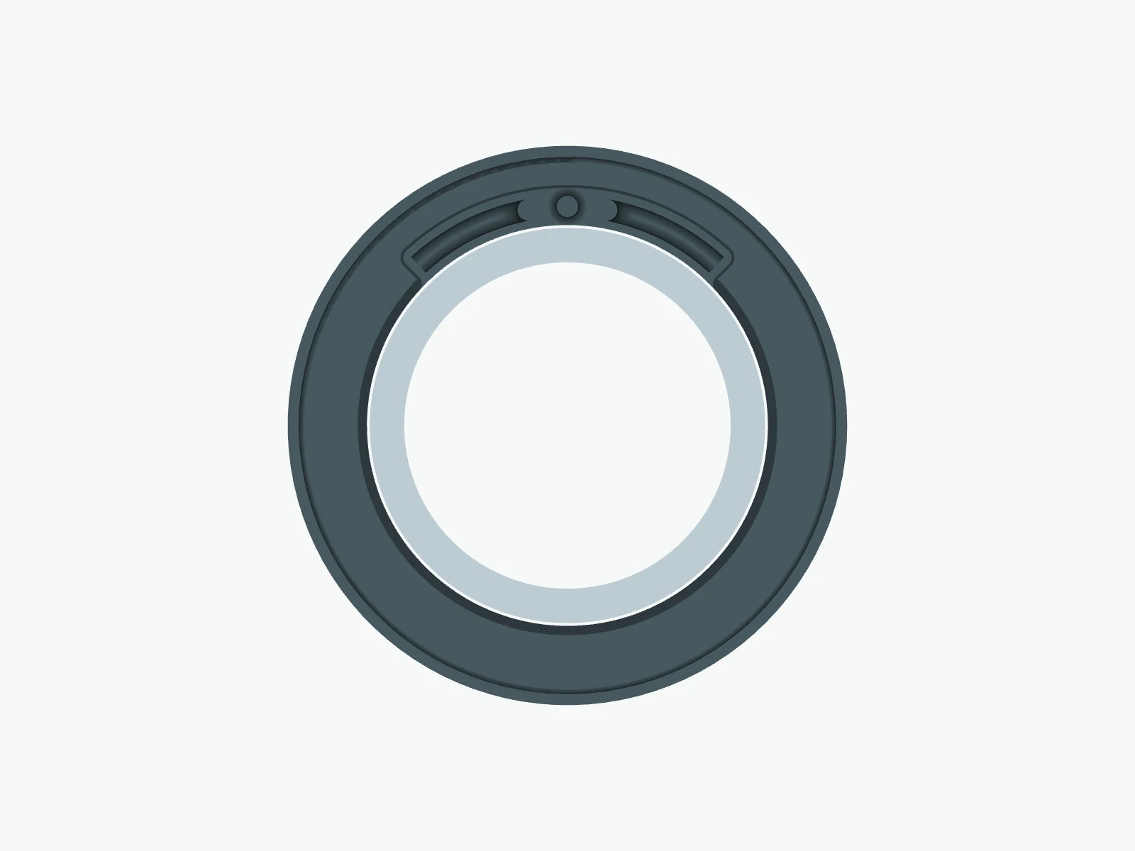
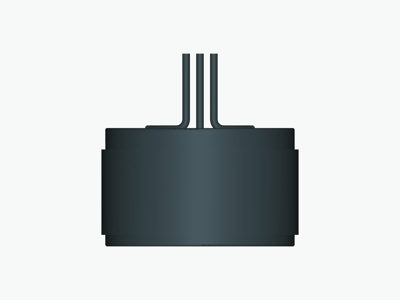
The FTM-R106 STEP and CAD views describe a shared mechanical reference, not winding internals or verified surface finishes. The CAD including modeled leads spans approximately 58.65 mm axially. The 200 mm lead-length reference is separate from that modeled envelope. 26 mm is the iron stack. The 36 mm body entry is a drawing reference, not an agreed installation limit. Budget the final body, leads, shaft retention and feedback before freezing the housing.
03 / Match the winding to the drive
Check the 12–48 V winding and the current definition.
A suitable bus voltage alone does not establish compatibility. Review the loaded torque-speed point, current convention, commutation, heat path and protection settings together.
| Parameter | Documented value / definition |
|---|---|
| Drive voltage range | 12–48 VTypical voltage 48 V; drive matching requires review |
| Rated output power | 150 W±10%; documented typical 48 V basis |
| Speed coefficient | 25 rpm/V±10%; documented unit |
| No-load speed | 1210 rpm±10%; not a loaded operating point |
| Listed loaded speed | 930 rpm±10%; load/drive/thermal point requires confirmation |
| Line resistance | 2.12 Ω±10%; measurement temperature not specified |
| Line inductance | 2.4 mH±10%; measurement frequency not specified |
| Torque constant | 0.32 N·m/A±10%; current convention must be checked with the drive |
| Back EMF constant | 0.37 V·s/rad±10%; electrical convention requires confirmation |
| Winding connection | Y starDocumented connection |
| Slots / rotor poles | 18 / 20 Documented arrangement |
| Mass | 311 g±10%; documented value |
| Rotor inertia | 32 kg·mm²±10%; documented value |
| Electrical time constant | 1.38 ms±10%; documented value |
| Motor constant | 0.295 N·m/√W±10%; documented value |
Plan the customer assembly around the motor kit
The reference geometry depicts a stator and a permanent-magnet rotor with modeled leads. Confirm the supplied lead arrangement, temperature sensor, potting and any accessories on the order drawing. Bearings, a customer shaft, housing, feedback device and servo drive are separate integration requirements, not confirmed included items.
Define stator-to-housing heat transfer, rotor retention, concentricity and air-gap control with your mechanical team. Establish feedback/commutation and temperature-sensor wiring with your drive supplier. No press-fit interference, adhesive process or assembly force is approved by this reference page.
Review the frameless motor installation checklist ↗Compare this frame’s winding options
FTM-R106: shared mechanical reference, separate drive review.
The listed winding options share the reviewed mechanical reference and revision shown below. Compare documented electrical entries with their conditions; a shared frame does not establish identical cooling, drive settings or interchangeability.
Engineering reviews remain open for the identified windings. This comparison does not confirm a housing fit or electrical setting. Resolve the relevant documentation questions before selection.
FTM-R106-W01 / FTM-R106-W02: Axial dimensions are documentation references for configuration discussion. The final body envelope, tolerances and lead exit must be specified on the configuration drawing; these references do not establish installation fit.
On narrow screens, scroll the table to view both winding columns.
| Parameter / operating basis | FTM-R106-W01 ↗ rev-a | FTM-R106-W02 ↗ rev-a |
|---|---|---|
| Drive voltage range | 12–48 V | 12–48 V |
| Speed coefficient | 25 rpm/V | 52 rpm/V |
| No-load speed | 1210 rpm | 2420 rpm |
| Listed loaded speed | 930 rpm | 2030 rpm |
| Line resistance | 2.12 Ω | 0.53 Ω |
| Line inductance | 2.4 mH | 0.6 mH |
| Torque constant | 0.32 N·m/A | 0.16 N·m/A |
| Back EMF constant | 0.37 V·s/rad | 0.18 V·s/rad |
| Winding connection | Y star | Y star |
| Mass | 311 g | 311 g |
| Rotor inertia | 32 kg·mm² | 32 kg·mm² |
| Continuous / 55°C winding temperature rise | 0.93 N·m / 2.04 A RMS | 0.93 N·m / 4.07 A RMS |
| Continuous / 105°C winding temperature rise | 1.55 N·m / 3.41 A RMS | 1.55 N·m / 6.82 A RMS |
| Peak / 10 seconds | 4.00 N·m / 9.13 A RMS | 4.00 N·m / 18.26 A RMS |
| Peak / 2 seconds | 6.50 N·m / 18.26 A RMS | 6.50 N·m / 36.63 A RMS |
No-load speed is not a loaded operating point. The listed loaded speeds have incomplete load, drive and thermal definitions. Compare torque constants only after checking the current convention; peak durations do not define a repeat/recovery cycle. Equal torque entries are not evidence of equal efficiency or identical test conditions. Use the individual datasheet and submit your loaded torque-speed point for a winding recommendation.
04 / Inspect the reference files
One winding datasheet. One clearly scoped mechanical CAD.
The datasheet identifies FTM-R106-W01; the STEP identifies FTM-R106 mechanical reference geometry. Confirm the applicable revision before using either as an order specification.
Stator & rotor CAD assembly
rev-a · 186.8 KB · Configuration reference · final order drawing required
Applies to: FTM-R106-W01, FTM-R106-W02 · FTM-R106 / rev-a · Shared mechanical reference; winding data is in each datasheet.
Download STEPFile identity & checksum
ftm-r106-mechanical.stp
338f83d1886f6cd177a4ae24d59cad1d08692bbb06e9e5ec3c34bdadccd22e5cW01 engineering datasheet
rev-a · 21.4 KB · Configuration reference · final order drawing required
Applies to: FTM-R106-W01 · FTM-R106 / rev-a
Download PDFFile identity & checksum
ftm-r106-w01-datasheet.pdf
8e4074d314204b3571e7b13c28455d37d8dbd15c6a24a5e98f503eaee42f7845Mechanical envelope sheet
rev-a · 89.8 KB · Configuration reference · final order drawing required
Applies to: FTM-R106-W01 · FTM-R106 / rev-a
Download PDFFile identity & checksum
ftm-r106-w01-outline.pdf
ec96df91bc5ef35123a22d9e3995255acc7cb7c10bd021b3cb739f6562a69874Supplier-provided engineering data, checked against the model documentation; not independently measured. The PDFs are independently composed reference documents. CAD export checks do not replace application or supplier revision approval.
05 / Review the configuration you need
Bring the winding, interfaces and leads into one engineering brief.
Customization starts with your constraints and a configuration review. The proposed design, sample requirements, quotation and confirmation drawing are then agreed for the project.
Winding and drive matching
Start from FTM-R106-W01; provide the loaded torque-speed point, DC bus, current convention, continuous duty and timed peaks/recovery. A custom winding is subject to configuration review.
Housing, shaft and axial interfaces
Provide maximum OD, required usable bore, shaft/rotor retention and complete axial/lead space. Agree the final envelope rather than using the reference body entry as an installation limit.
Lead arrangement and sensing
Specify exit direction, actual cable length, connector and temperature/feedback needs. Confirm supplied components and accessories for the quoted configuration.
- 01Share the duty and envelope
- 02Review winding and interfaces
- 03Confirm drawing and sample plan
- 04Freeze the order configuration
06 / Resolve the remaining questions
Before you specify FTM-R106-W01.
What does the 26 mm stack mean for FTM-R106-W01 installation?
26 mm is the iron stack. The 36 mm body entry is a drawing reference, not an agreed installation limit. Budget the final body, leads, shaft retention and feedback before freezing the housing. The 35 mm bare rotor bore must also accommodate the customer shaft and retention features.
Which continuous torque reference should I use for FTM-R106-W01?
FTM-R106-W01 documents 0.93 N·m at 2.04 A RMS for 55°C winding rise, and 1.55 N·m at 3.41 A RMS for 105°C rise. These are temperature rises above ambient, not absolute winding limits or guaranteed output in your housing.
Can FTM-R106-W01 repeat its 6.5 N·m peak?
The 4 N·m reference belongs to 10 seconds at 9.13 A RMS; 6.5 N·m belongs to 2 seconds at 18.26 A RMS. Repetitive duty requires a defined repeat/recovery cycle, heat path, ambient and drive review.
Does 1210 rpm establish a loaded operating point?
1210 rpm is the documented no-load reference. The separate 930 rpm loaded-speed entry has no complete approved torque/drive/thermal point. Neither entry supplies a continuous torque-speed curve or a speed guarantee at the listed torque.
What do the FTM-R106-W01 PDF and STEP describe?
The PDF identifies this winding reference; the FTM-R106 STEP is shared mechanical reference geometry for the listed windings. CAD lead shape and neutral colors are not production cable length or finish specifications. The axial envelope remains subject to the final configuration drawing.
Can FTM-R106-W01 be customized, and what should I send?
Request a configuration review with FTM-R106-W01 / rev-a, loaded torque and speed, peak duration/recovery, bus/current definitions, housing heat path, available OD/bore/axial space, lead/sensor needs and quantities. Winding and interface changes, supplied components and delivery terms are agreed for the reviewed configuration.
07 / Start with this model
Request a FTM-R106-W01 fit & winding review.
The form starts with the public model and revision. Add your actual operating point, cooling, envelope and quantities so the response can address the configuration you need.
Samples, MOQ, lead time and pricing are quoted against the reviewed requirements.
Compare other mechanical references in this frame
Review the envelope before comparing torque.
These references use other axial configurations in the same stator diameter. Listed temperature rises share a label; identical cooling and test conditions have not been established. No replacement equivalence is implied. Use the full selector for other frame sizes.
| Model / revision | OD / bore / stack | Body maximum / lead space | Documented continuous torque |
|---|---|---|---|
| FTM-R104-W01 ↗ rev-a | 60 / 35 / 13 mm | ≤23 mm bodyLeads need separate review; documentation discrepancy open. | 0.47 N·m at 55°C rise0.78 N·m at 105°C rise |
| FTM-R104-W02 ↗ rev-a | 60 / 35 / 13 mm | ≤23 mm bodyLeads need separate review; documentation discrepancy open. | 0.47 N·m at 55°C rise0.78 N·m at 105°C rise |
| FTM-R105-W01 ↗ rev-a | 60 / 35 / 20 mm | ≤30 mm bodyLeads need separate review; documentation discrepancy open. | 0.72 N·m at 55°C rise1.19 N·m at 105°C rise |
| FTM-R105-W02 ↗ rev-a | 60 / 35 / 20 mm | ≤30 mm bodyLeads need separate review; documentation discrepancy open. | 0.72 N·m at 55°C rise1.19 N·m at 105°C rise |
Review this motor inside your assembly
Keep the model revision and stated rating conditions with your installation, drive and cooling requirements.
Look up a model, screen the envelope and compare winding referencesUse the record’s revision and open reviews; a shortlist is not engineering confirmation.